3-8
Cisco uBR-3x10 RF Switch Hardware Installation and Cabling Guide
OL-1984-06
Chapter 3 Installing the Cisco RF Switch
Rack-Mounting the RF Switch with the Cisco uBR10012 CMTS
Installing the Cable Management Bracket on the Cisco uBR10012 Router
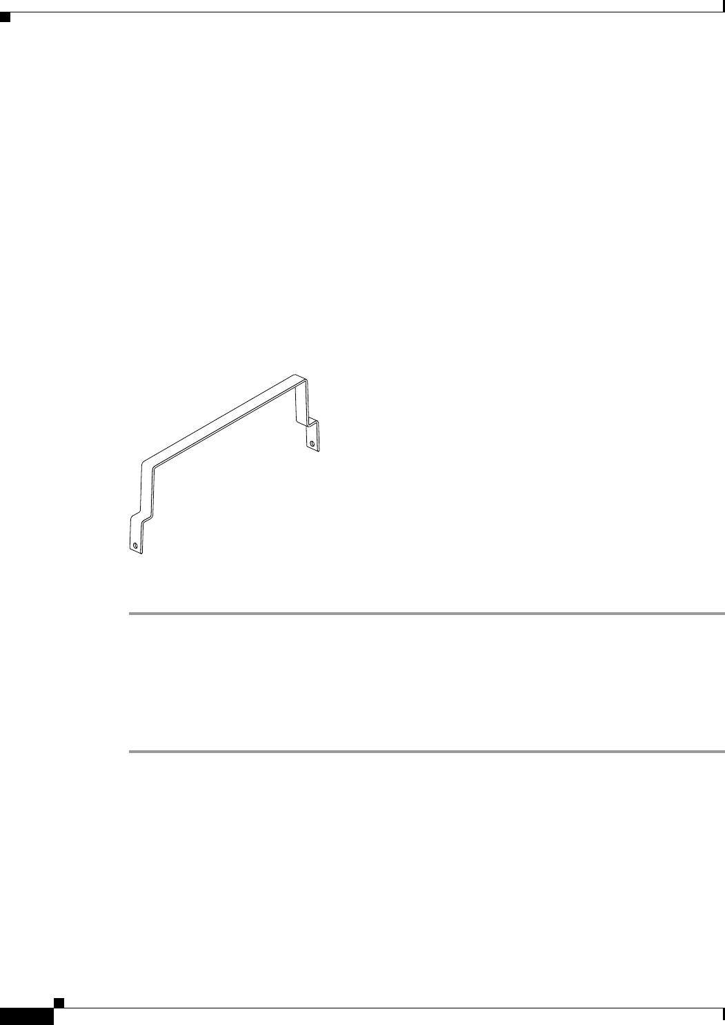
The cable management bracket for Cisco uBR10012 CMTS chassis is enclosed in the shipping container
with your Cisco uBR 3x10 RF Switch. (See Figure 3-4.) Installation of the bracket is optional, however,
we recommend using this bracket to ensure proper airflow in the chassis.
Ensure that the bracket is connected before you proceed with connecting RF cables to the cable interface
line cards installed in your Cisco uBR10012 chassis. See Figure 3-1 on page 3-4 and Figure 3-2 on
page 3-5 for illustrations of the cable management bracket’s location on the Cisco uBR10012 chassis.
Equipment
• Cable management bracket (Cisco part number 700-14066-01)
• Two M5 x 8-mm Phillips countersunk screws
• Number two Phillips screwdriver (extended length)
Figure 3-4 Optional Cable Management Bracket for the Cisco uBR10012 CMTS Chassis
To install the cable-management bracket, complete the following steps:
Step 1 Locate the threaded holes in the top-right-rear and top-left-rear side of the Cisco uBR10012 chassis
(spanning the width of the cable interface line cards on the chassis).
Step 2 Align the cable-management bracket with one set of threaded holes at the top of the Cisco uBR10012
chassis.
Step 3 Thread M5 x 8-mm Phillips countersunk screws through the bracket and into the chassis.
Step 4 Use a number 2 Phillips screwdriver to tighten the screws.


