


■
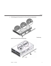
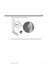
Always load equipment into a rack from thebottom up so thatit will not become top-heavy
and tip over. Deploy theanti-tip bar to theprevent the rack fromtipping during equipment
installation.
■
Ensure that the temperature in the rack doesnot exceed the controller'smaximum ambient
rated temperatures. Consider the total airow requirements of all equipmentinstalled in the
rack to ensure that the equipment is operatedwithin its specied temperaturerange.
■
For best results, only qualied Sun service personnel shouldperform cluster installation and
conguration. Contact Sun Service for assistance.
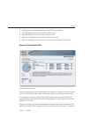
Prerequisites
Refer to the poster that shipped with theproduct or the followinghardware service sections
located on
http://wikis.sun.com/display/shworks (http://wikis.sun.com/display/
fishworks)
for an overview of your system controller.
■
7110 Overview - view component diagramsand specications
■
7210 Overview - view component diagramsand specications
■
7310 Overview - view component diagrams,specications, and cluster options
■
7410 Overview - view component diagrams,specications, and cluster options
If you intend to install diskshelves into the same rack, refer tothe
Disk Shelf Installation section
(applies to J4400 and J4500) for how toinstall them into thebottom of your rack.
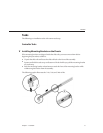
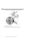
Check that your rack is compatible with theslide rail and cable management assembly options
as follows:
■
The structure is a four-post rack with mountingat both front andback. Two-post racks are
not compatible.
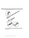
■
The horizontal opening and unit vertical pitch conformsto ANSI/EIA 310-D-1992 or IEC
60927 standards.
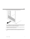
■
The distance between the front and back mountingplanes is between 24inches and 36
inches (610 mm to 915 mm).
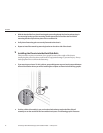
■
The distance to the front cabinet door, providingclearance depth in frontof the front
mounting plane, is at least 1 inch (25.4mm).
■
The distance to the back cabinet door, providingclearance depth behind thefront mounting
plane, is at least 31.5 inches (800 mm)with the cable managementassembly, or 27.5 inches
(700 mm) without the cable management assembly.
■
The distance between structural supports and cable troughs,providing clearance width
between the front and back mounting planes, isat least 18 inches(456 mm).
Controller
SunStorage7000UniedStorageSystemInstallationGuide • February201014