


7870 Interfacility Link Installation and User’s Guide page 39
Foxcom proprietary information
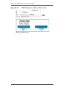
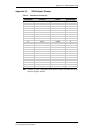
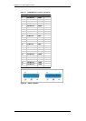
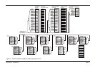
Appendix 4 Pinout Charts and Diagrams
Figures 31 through 36 give detailed pinout information for the 7180M chassis, the 2380
Relay Adaptor and the 2040 RF Switch.
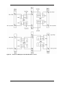
Figure 31 Standard 7180M and 7180M with 2380 Relay Adapter Pinout . . . . . . . . . . . . . . . . . . . 40
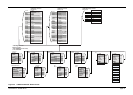
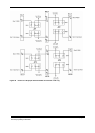
Figure 32 7180M and 2040 RF Switch Pinout . . . . . . . . . . . . . . . . . . . . . . . . . . . . . . . . . . . . . . . . 41
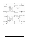
Figure 33 Pinout of 7180M Jumper with 2040 RF Switch in slots 2 and 5 . . . . . . . . . . . . . . . . . . . 42
Figure 34 Pinout of 7180M jumper with 2040 RF switch in slot 5. . . . . . . . . . . . . . . . . . . . . . . . . . 43
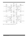
Figure 35 Pinout of 7180M jumper with 2040 RF switch in slot 5. . . . . . . . . . . . . . . . . . . . . . . . . . 44
Figure 36 Pinout of 7180 jumper with transmitter and receiver units only . . . . . . . . . . . . . . . . . . . 45