


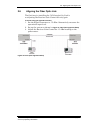

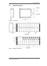

2.5 Connecting the Back Panel Jumpers
7870 Interfacility Link Installation and User’s Guide page 13
Foxcom proprietary information
2.5 Connecting the Back Panel Jumpers
On the rear panel of the 7180M Back Panel are product selectors (JP1 to JP4). The 3 pin selectors (male) are the
connecting point between the slots and the back panel. One pin is for the transmitter/receiver (Tx/Rx), one is for the
optional 2040 1:1 Redundant Switch, and one is for the 7180M. A 2 pin jumper (female) is placed on the relevant pins to
complete the connection between the 7180M and the units. For example, if a 2040 Switch is being used, the jumper is
placed on the Switch-7180M pins.
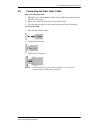
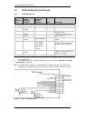
To connect the jumpers:
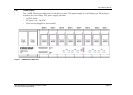
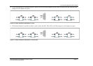
1. Each jumper has two sets of pins, upper and lower. The upper pins are labeled SW (Switch) and the lower pins Tx/Rx.
2. If the 7180M has Tx or Rx units only, place all jumpers on the lower two pins.
Figure 8 Jumper Installation: Tx and Rx only
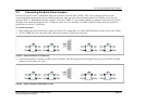
3. If the 2040 Switch is installed in Slot 2, place the JP1 and JP2 jumpers on the higher two pins and the JP3 and JP4
jumpers on the lower two pins.
Figure 9 Jumper Installation: 2040 Switch in slot 2