


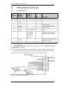
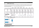
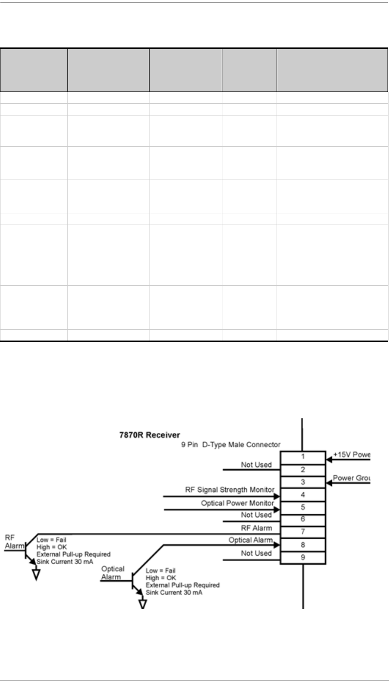
3.3 7870 Interfacility Link Pinouts
7870 Interfacility Link Installation and User’s Guide page 21
Foxcom proprietary information
3.3.2 Receiver Pinouts
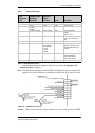
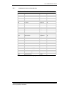
Note If a 2380 Relay Adapter is installed RF and Optical Levels are measured
together; the alarm indicates a problem in either the RF or optical levels.
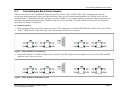
Figure 16 7870R Receiver pinout
Caution
When monitoring the voltage outputs use only a high resistance DVM.
Standalone
9 Pin
Connector
[J14]
7180M Chassis
Backplane
Connector
2380 Relay
Adapter
Connector
Name Description
1 — — +14V Power 350 mA
2 — — Spare Not Used
3J11-P9
J12-P25
J13-P25
J4-P25 GND Chassis Ground
4 J13-P1 to J13-P8 J4-P1 to J4-P8 RSSI RF signal strength
indicator:
range 0.2 - 10 V
5 J13-P9 to J13-P16 J4-P9 to J4-P16 PDI Indicates input optical
power: 1 V/ 1 m optical
power
6 — — Spare Not used
7 J12-P1 to J12-P8 J2: P1-P2
P3-P4, P5-P6
P7-P8, P9-P10
P11-P12
P13-P14
P15-P16
RFA RF Alarm: Open collector
interface.
1
Sinks current
when RF level is low, up
to 30 mA.
8 J12-P9 to J12-P16 See note below OPTA Optical Alarm: Open
Collector Interface
1.
.
Sinks current at low
optical, up to 30 mA.
9 — — Spare Not used
Table 5 7870R Receiver Pinout
1. If the 2380 Relay Adapter is installed, the alarms are dry contact. See Appendix 3 The
2380 Relay Adapter on page 33.