


2.1 Setting up the Transmitter
page 8 Document no. 93-005-35-C5
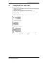
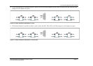
2.1 Setting up the Transmitter
1. Place the 7870T in the 7180M Chassis.
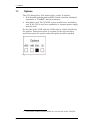
2. Apply AC power to the chassis. The Power Supply and Laser
LEDs should be lit.
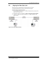
3. Using an optical power meter, measure the optical power. Insert
the meter’s cable into the Transmitter’s optical connector. Power
levels should be 0.5 mW minimum (-3 dBm).
Alternatively, use a DVM to measure the voltage at:
•
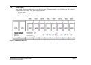
7180M Rackmount: Pins J13-P17 through J13-P24 for the slot
being measured (See
Table 4 7870T Transmitter Pinout on page20
for details regarding J13 pinouts). [7180M Rackmount]
• Standalone: At pin #6 of the 9 pin connector [Standalone]
The signal level should be -4.5 ± -0.3VDC.
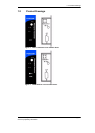
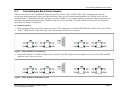
4. On the rear panel, connect the coax cable to the RF Input
Connector. The RF LED should be lit.
5. On the rear panel, connect the fiber optic cable to the Optical
Connector.
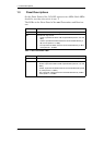
Note If either LED is not lit, see Chapter 4 Troubleshooting on page25.
Caution When monitoring the voltage outputs use only a high
resistance DVM.