


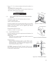
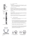
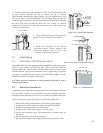
The orientations are shown in the DSAPilot graphics. When activated by
the DSAPilot software, this LED can be used to verify both the correct
up-down orientation and, when multiple modules are used, the correct
location of each. For the DSA250i, the Power End is the end with the HF
subsystem and Signal End is the end with the LF subsystem.
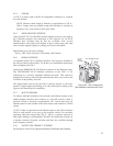
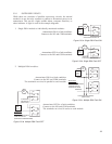
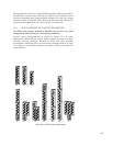
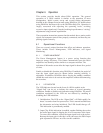
5.6.3 MULTIPLE MODULES AND CLUSTER CONFIGURATIONS
CAUTION: Only clusters included in DSAPilot may be used. Any other
configurations will result in poor to unusable performance.
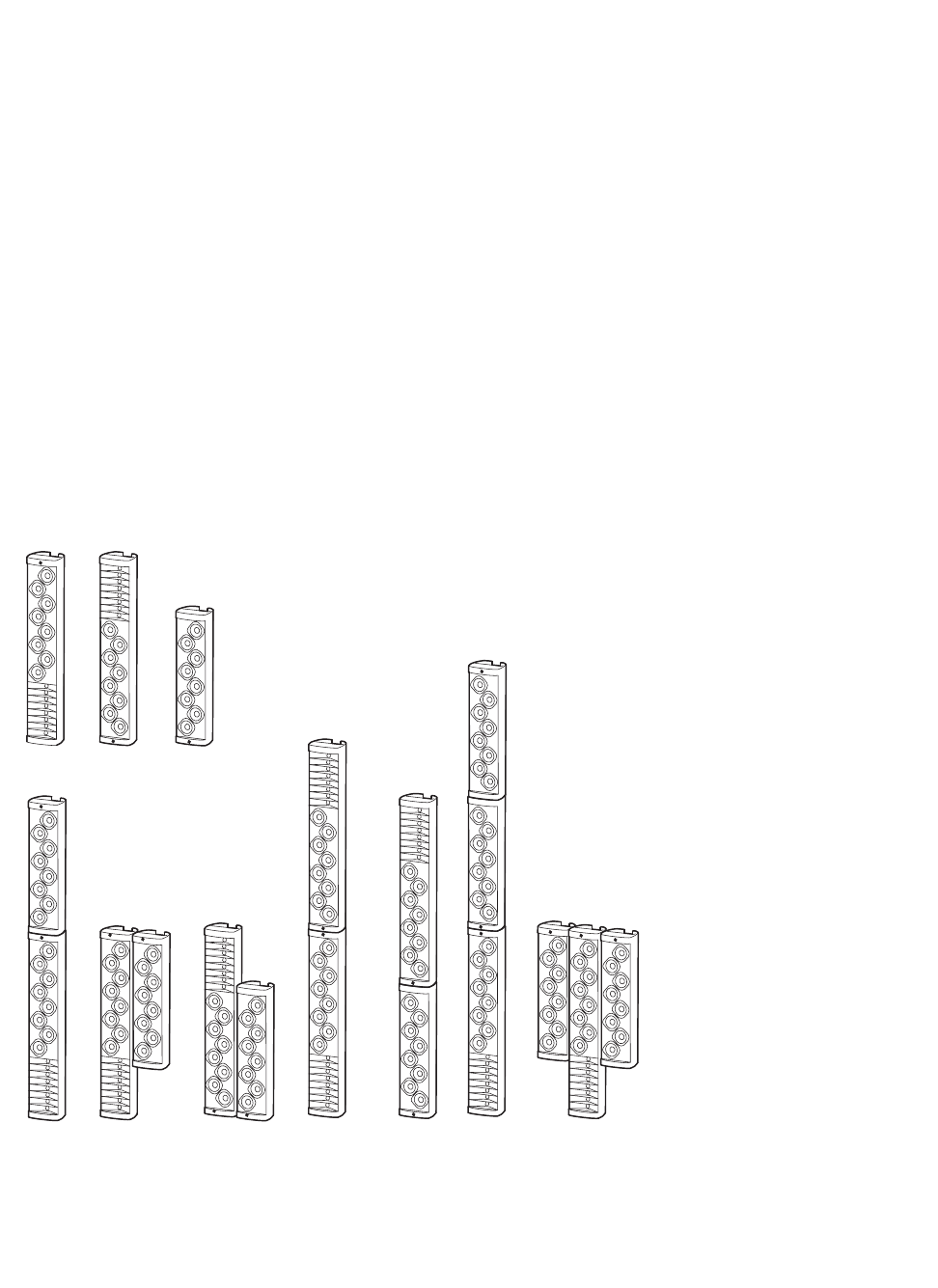
Several cluster configurations are shown in Figure 5.6.3. In some
applications, tighter pattern control, higher output, or narrower vertical
coverage may be desirable. Because of these and other possible
requirements, DSAPilot allows several cluster configurations to be used
in a single or in multiple locations to achieve various coverage and
output results.
23
1A
1B
1C
2A
2C
2D
2F
3A
2H
3T
Figure 5.6.3 DSAi Cluster Configurations