


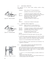
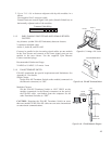
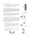
5.3.3 SUPERVISORY CIRCUITS
While there are a number of possible supervisory circuits, the normal
method is to use the relay contacts to connect or disconnect power to an
annunciator. This can be a light, audible alarm, computer interface, or
other indicator. A light is used in the example diagrams.
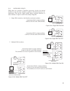
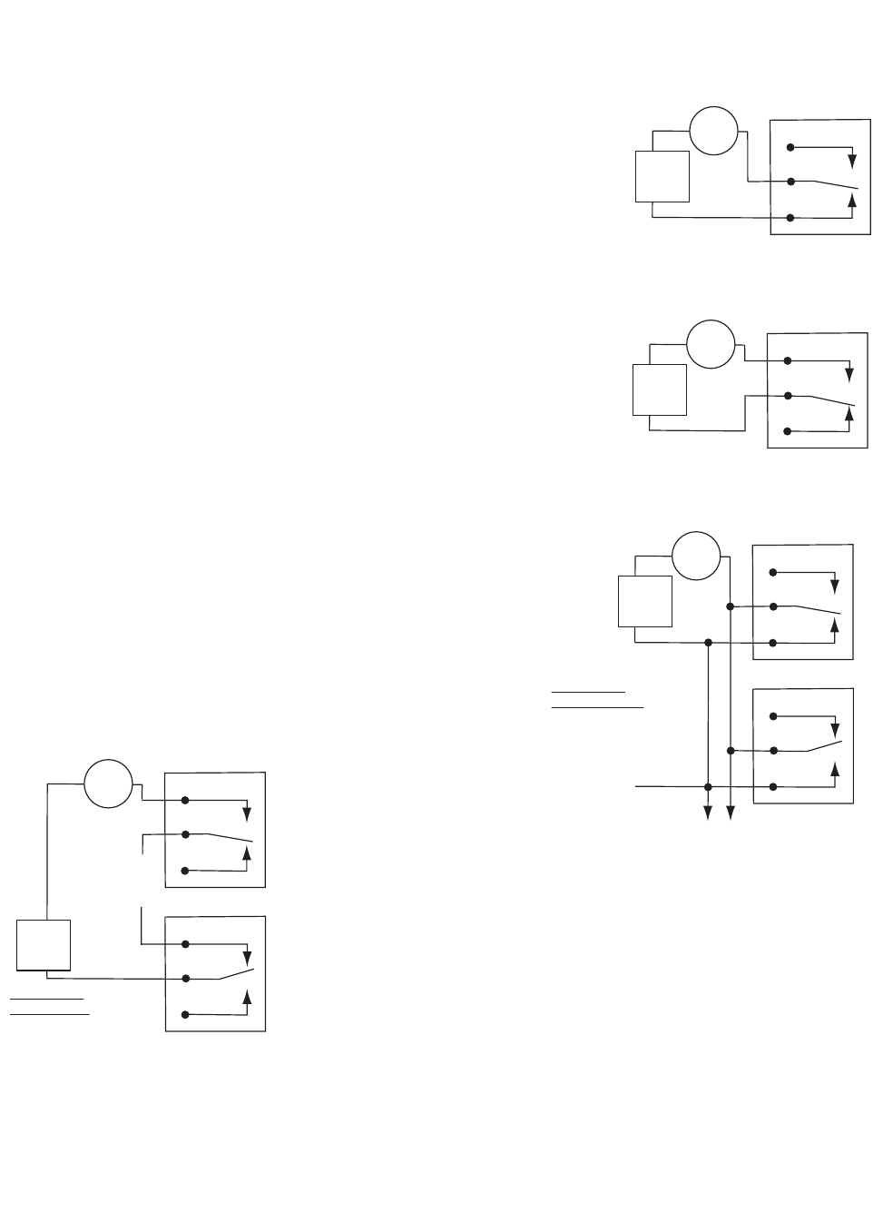
1. Single DSAi module or individually monitored modules:
Annunciator ON for a fault condition:
Connect to the NC and COM terminals.
Annunciator OFF for a fault condition:
Connect to the NO and COM terminals
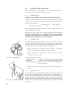
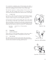
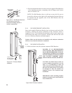
2. Multiple DSAi modules:
Annunciator ON for a fault condition:
Connect to the NC and COM terminals.
The terminals are wired in parallel to each module.
19
NO
COM
NC
AC/DC
MAX
30 V, 1 A
LIGHT
ON
SINGLE DSA
A FAULT TURNS THE LIGHT ON
NO
COM
NC
AC/DC
MAX
30 V, 1 A
LIGHT
OFF
SINGLE DSA
A FAULT TURNS THE LIGHT OFF
Figure 5.3.3a Single DSAi Fault ON
Figure 5.3.3b Single DSAi Fault OFF
NO
COM
NC
AC/DC
MAX
30 V, 1 A
LIGHT
OFF
MULTIPLE DSA
SERIES WIRING
A FAULT IN ANY DSA MODULE
TURNS THE LIGHT OFF
(LOWER RELAY SHOWN ENERGIZED)
NO
COM
NC
TO ADDITIONAL
DSA MODULES
(DSA2 TO DSAn)
NO
COM
NC
AC/DC
MAX
30 V, 1 A
LIGHT
ON
MULTIPLE DSA
PARALLEL WIRING
A FAULT IN ANY DSA MODULE
TURNS THE LIGHT ON
(LOWER RELAY SHOWN
ENERGIZED)
NO
COM
NC
TO ADDITIONAL DSA MODULES
(DSA2 TO DSAn)
Figure 5.3.3d Multiple DSAi Fault OFF
Figure 5.3.3c Multiple DSAi Fault ON
Annunciator OFF for a fault condition:
Connect to the NO and COM terminals.
The terminals are wired in series to each module.