


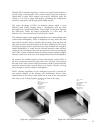
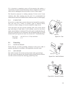
2. Up to 2 ft / 0.6 m between adjacent side-by-side modules in a
cluster
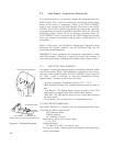
User-supplied Cat-5 crossover cable.
Connect between unused Signal Link jacks (Neutrik EtherCon) on
horizontally adjacent ends of the modules.
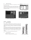
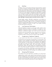
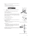
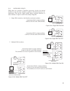
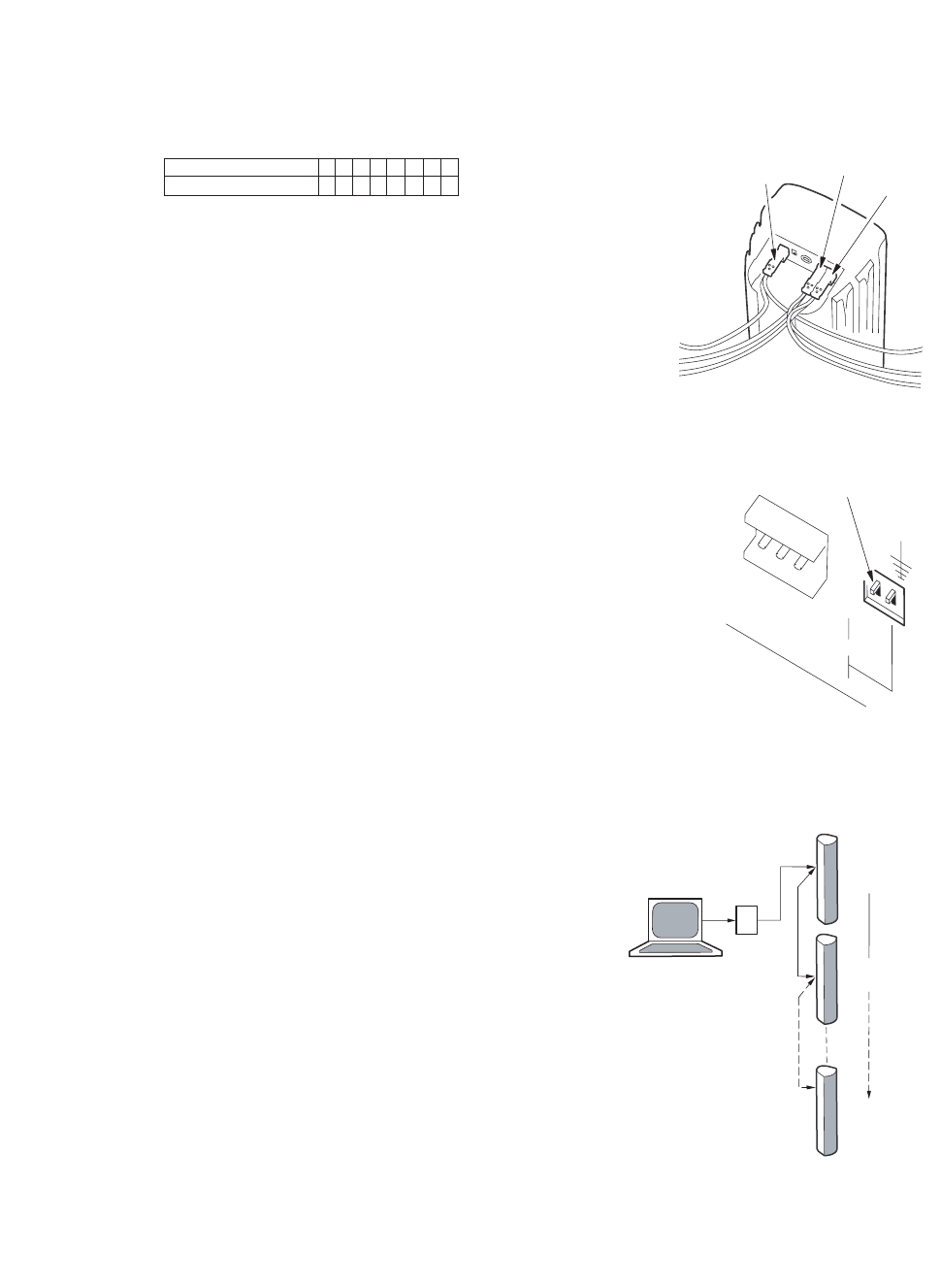
5.1.5 DAISY CHAINING COMPUTER AND AUDIO SIGNALS BETWEEN
CLUSTERS
Any distance (within EIA-485 limitations) between clusters:
2-conductor shielded cable
Audio A, Audio B, and EIA-485
Connect in parallel to the incoming signal cables on one module
in the first cluster and connect to the same signal ports on one
module in the next cluster. Use the supplied 3-pin Phoenix
Contact terminal plugs.
Recommended Conductor Gauge:
24 AWG to 18 AWG / 0.2 mm to 1 mm
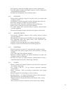
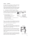
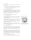
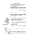
5.1.6 EIA-485 TERMINATE SWITCH
EIA-485 termination has special requirements and limitations. See
Appendix 8.3 for details.
Single Cluster:
Set the EIA-485 Terminate Switch on the module (connected via
the Phoenix connector) to “ON”.
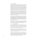
Multiple Clusters:
Set the EIA-485 Terminate Switch to “ON” ONLY on the
module (connected via the Phoenix connector) at the end of
the EIA-485 cable run furthest from the computer. Set all
other Terminate Switches to “OFF”.
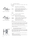
CAUTION: Engaging the EIA-485 Terminate Switch on more
than one module on the EIA-485 cable run can cause intermittent
or nonexistent communications.
15
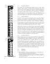
Crossover Cable Wiring
STANDARD END PINS 1 2 3 4 5 6 7 8
CROSSOVER END PINS 3 6 1 4 5 2 7 8
EIA-485
AUDIO A
AUDIO B
Figure 5.1.5 Linking > 2 ft / 0.6 m
EIA-485 TERMINATE SWITCH
EIA-485
TERMINATE
AUDIO
GROUND
LIFT
ON
OFF
LIFT
Figure 5.1.6a EIA-485 Terminate Switch
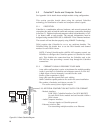
RS-232
OR USB
TO EIA-485
CONVERTER
PC
DSA
CLUSTERS
TERMINATE
SWITCH "OFF"
TERMINATE
SWITCH "OFF"
TERMINATE
SWITCH "ON"
Figure 5.1.6b EIA-485 Network Diagram