


Chapter 5 Installation
This chapter details the requirements for installation. Specific details
may require some variation depending on the particular situation.
However, the basic requirements are the same in all cases.
Module refers to either a DSA230i or DSA250i. Cluster refers to any of
the permissible arrangements of single or multiple DSA230i or DSA250i
modules as defined in DSAPilot. Whether they consist of a single or
multiple modules, all DSAi clusters function as a single loudspeaker.
5.1 Analog Audio and EIA-485 Computer Control
This section details the electrical requirements for
installing the module. Specific cabling details may require
some variation depending on the particular situation.
However, the basic requirements are the same in all cases.
Basic electrical installation tasks include:
Audio signal connection:
This can be standard analog (Section 5.1.2) or
digital using CobraNet[TM] (Section 5.2)
Computer control connection:
This can be EIA-485 (Section 5.1.3) or CobraNet (Section 5.2)
Supervisory relay connection:
As required to monitor the module status
There are several possible types and combinations for the audio and
computer control connections. This and the following section cover the
most common connections. For other combinations and details about
multiple module wiring configurations see Appendix 8.6.
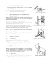
5.1.1 CABLE ROUTING CONSIDERATIONS
The configuration and orientation of the modules will determine where
signal, computer, and ac mains cabling must be connected to the
modules. For certain cluster configurations it may be necessary to route
cabling from one end of a module to another.
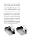
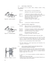
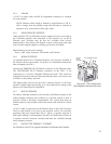
The main cable routing method is to use the channels in the heat sink
extrusion that forms the rear of the DSA250i and DSA230i enclosures.
These channels are intended to be used to route and conceal cabling the
length of the enclosure as required. In this way, single wall outlet
locations for audio, computer, and ac mains can easily service a single
module or cluster.
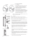
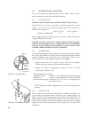
To facilitate cable routing, clusters have been arranged, where possible,
so the Power Ends of the enclosures are adjacent. This minimizes the
routing of ac mains cables, which are typically larger and may be more
difficult to thread into the extrusion than signal cables.
13
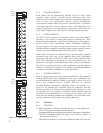
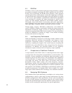
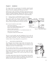
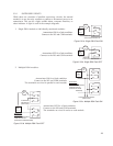
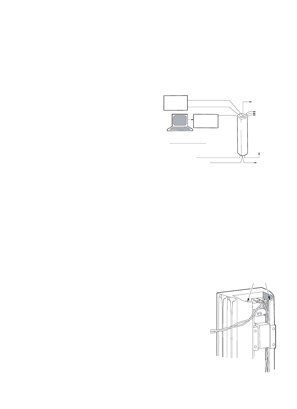
SIGNAL LINK
CABLE TO
ADJACENT DSA
MODULES
SIGNAL LINK CABLE TO
ADJACENT DSA
MODULES
AC MAINS*
(115V OR 230V
)
TO EIA-485
CONVERTER*
EIA-485*
CABLE
AUDIO B CABLE (IF USED)*
PC*
DAISY-CHAIN
CABLE TO DSA
MODULES
DSA
LINE LEVEL
AUDIO
SOURCE(S)*
RS-232
AUDIO A CABLE*
*SUPPLIED BY THE USER
DAISY-CHAIN
CABLE TO DSA MODULES
FAULT DETECT CIRCUIT
Figure 5.1 Electrical Block Diagram
CABLE CHANNELS
Figure 5.1.1 Cable Channels