


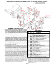
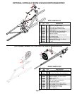

REF. PART
NO. NO. QTY. DESCRIPTION
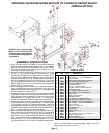
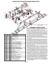
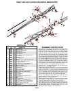
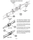
RIGHT AND LEFT OUTER WING PARTS BREAKDOWN
Page 7
Please order replacement parts by PART NO. and DESCRIPTION.
1. 03322 1 Left Inner Wing
2. 03323 1 Right Inner Wing
3. 03328 2 Right and Left Outer Wing
4. 03326 2 Breakaway Pin
5. 03325 2 Outer Breakaway Hinge
6. 03329 2 Outer Hinge Pin
7. 04051 4 5/8"-11UNC x 1-1/2" Hex Head Bolt Gr.5
8. 00085 4 1/2" Flatwasher
9. 00490 4 Breakaway Bearing
10. 03327 2 Lock Collar
11. 05318 2 Spring
12. 00694 6 1/4"-20UNC x 1/2" Square Head Set Screw
13. 02772 8 1/4"-20UNC Nylon Insert Locknut
14. 00640 6 1/2"-13UNC Jam Nut
15. 00967 4 1/2"-13UNC x 1-1/4" Hex Head Bolt Gr.5
16. 02178 2 1/2"-13UNC Nylon Insert Locknut
17. 05309 2 Wing Latch Handle
18. 00080 2 7/16" x 1-1/4" lg. Clevis Pin
19. 00059 2 3/8" Flatwasher
20. 00185 2 5/32" x 1" lg. Cotter Pin
21. 05310 2 Wing Latch Channel
22. 04221 2 5/16"-18UNC x 2-1/2" Hex Head Bolt Gr.5
23. 02802 18 5/16"-18UNC Nylon Insert Locknut
24. 03320 2 Latch Bolt
25. 00004 4 5/16" Flatwasher
26. 05297 2 Tip Protector
27. 00909 8 5/16"-18UNC x 1-1/4" Square U-bolt
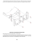
28. 03439 1 Storage Bracket
29. 04642 4 Zerk
30. 05319 2 Tip Offset Bracket
31. 04822 4 1/4"-20UNC x 1-1/16" Square U-bolt
32. 05171 2 Wing Tip Extension for 50' boom (optional)
33. 00209 2 3/8"-16UNC x 1" Square Head Set Screw
34. 00199 1 Lock Pin (3/8"O.D. x 3-1/2" lg.)
35. 00182 1 1/8" Small Hairpin
36. 03537 2 Gusset Plate
PARTS LIST
ASSEMBLY INSTRUCTIONS
1. Attach the outer wing (#3) to the breakaway hinge (#5). Place
bearings (#9), 1/2" flatwashers (#8) and 1/2" x 1-3/4" bolts (#7) to
the outer wing (#3). Slide outer wing (#3) on to the breakaway
hinge (#5). Insert breakaway hinge pin (#4) through the outer
wing top bushing through the breakaway hinge top bushing,
through the lock collar (#10), through the 1/2" flatwasher, spring
(#11) and 1/2" flatwasher (#8), through the bottom bushing on the
outer wing and through the breakaway hinge, place 1/2" locknut
(#16) on the hinge pin (#4) do not tighten. Tighten the 1/4" x
1/2" sq. head setscrew (#12) on the lock collar (#10), now tighten
the 1/2" locknut (#16) to compress breakaway spring, the spring
should be compressed to about 3-1/4". Do not over compress.
2. Assemble the outer wing and breakaway hinge to the inner left
and right wing (#1 & 2). Insert hinge pin (#6) through the bushings
and secure using 1/4" x 1/2" square head set screw (#12).
3. Insert four 1/2" x 1-1/4" bolts (#15) and four 1/2" jam nut (#14) into
the inner left and right wing (#1 & 2).
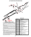
4. Assemble the wing latch handle (#17) to the inner right and left
wing (#1 & 2) using the 7/16" clevis pin (#18), 3/8" flatwasher (#19)
and secure with 5/32" x 1" cotter pin (#20). Next attach the wing
latch channel (#21) to the wing latch handle (#17) using one 5/16"
x 2-1/2" bolt (#22), two 5/16" flatwashers (#25) and one 5/16"
locknut (#23). Next screw the tee bolt (#24) into the wing latch
channel (#21) and secure with 1/2" nut (#14) on back side.
5. Bolt the wing storage bracket (#28) to the right inner wing
approximately 30" from latch plate, using two 1/4" x 1-1/16" sq. U-
bolt (#31) and four 1/4" locknuts (#13).
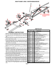
6. Bolt the wing tip protector (#26) to the outer right and left wing (#3)
approximately 17" from wing tip. Secure using four 5/16" x
1-3/8" sq. U-bolts (#27) and eight 5/16" locknuts (#23).
7. Attach the gusset plate to the bottom wing tube and the nozzle
tube, center them as close as possible, between the hinge points
and the welded in gusset. Attach them using one 5/16" x 1-1/4"
Square U-bolt (#27), two 5/16" Locknuts (#23), one 1/4" x 1-1/16"
Square U-bolt (#31) and two 1/4" Locknuts (#13).
22
25
5
29
20
19
32
1
29
17
18
23
14
21
24
4
9
7
7
9
16
8
12
11
15
6
14
10
8
29
3
23
25
27
30
12
26
23
33
27
2
31
27
25
23
28
31
34
35
36
13
23
27
13
29
29
30
25
14
24
22
23
21
20
16
19
14
17
12
12
12
8
8
11
6
7
9
9
7
3
4
29
10
5
13
23
36
31
27
18
15