


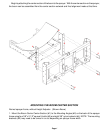
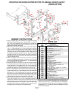
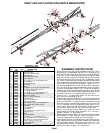
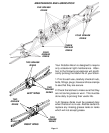

MOUNTING THE BOOM CENTER SECTION TO MANUAL HEIGHT ADJUST
2
2
3
5
5
5
5
5
3
3
3
6
7
9
11
13
15
16
16
17
17
18
2
19
24
24
29
30
5
4
9
23
9
2
23
27
26
25
1
3
5
3
3
5
16
14
12
10
6
2
19
16
17
17
19
7
3
2
17
16
5
5
31
9
25
26
27
2
20
5
22
3
2
4
5
3
18
17
16
15
3
5
18
8
28
5
5
29
24
(DFBHA OPTION)
8
21
27
25
26
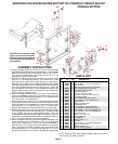
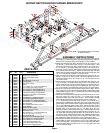
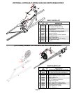
REF. PART
NO. NO. QTY. DESCRIPTION
PARTS LIST
1. 05601 1 Height Adjuster Main Frame
2. 00523 23 3/8"-16UNC x 1-1/4" Hex Head Bolt Gr. 5
3. 00059 23 3/8" Flatwasher
4. ---- 2 Boom Mounting Brackets (not included)
5. 02592 33 3/8"-16UNC Nylon Insert Locknut
6. 03340 2 Lock Pin Bracket
7. 03306 1 Boom Carrier
8. 00967 6 1/2"-13UNC x 1-1/4" Hex Head Bolt Gr.5
9. 02178 7 1/2"-13UNC Nylon Insert Locknut
10. 02363 2 5/32" x 1/14" Cotter Pin
11. 00205 2 7/16" Flatwasher
12. 02208 2 Lock Spring
13. 03099 2 Roll Pin (3/16" x 1")
14. 03342 2 Lock Pin
15. 03305 2 Boom Carrier Brackets
16. 02946 8 UHMW Wear Pad
17. 05732 16 1/4"-20UNC x 1" Slotted Flat Head
18. 00062 16 1/4"-20UNC Hex Nut
19. 00914 6 3/8"-16UNC x 1-1/2" Hex Head Bolt Gr.5
20. 03345 1 Winch Mount Bracket
21. 00084 2 1/2" Lockwasher
22. 04967 1 Winch w/ disc brake - 1200 lb. cap. (w/ handle)
- 04971 1 Replacement Handle only
23. 05607 2 Top Pulley Mount
24. 00482 3 1/2"-13UNC x 1-3/4" Hex Head Bolt Gr.5
25. 01838 3 Cable Retainer Bracket
26. 01839 3 1/2" I.D. x 5/8" lg. Spacer
27. 01840 3 Pulley
28. 05609 1 Bottom Pulley Mount
29. 01887 2 3/8"-16UNC x 2-1/2" U-bolt
30. 04819 1 5/16" Rapid Link
31. 05611 1 3/16" Aircraft Cable x 20' lg. with thimble
Please order replacement parts by PART NO. and DESCRIPTION.
7. Attach the winch mounting bracket (#20) to the height adjust main
frame (#1) using two 1/2" x 1-1/4 bolts (#8) and two 1/2" lockwashers
(#21). Mount the winch (#22) to the winch mounting bracket (#20),
using three 3/8" x 1-1/4" bolts (#2), three 3/8" flatwashers (#3) and
three 3/8" locknuts (#5).
1. Mount the height adjust main frame (#1) to the boom mounting
brackets (#4) on the sprayer frame with eight 3/8" x 1-1/4" bolts
(#2), eight 3/8" flatwashers (#3) and eight 3/8" locknuts (#5).
NOTE: The mounting brackets (#4) may need to be turned in or out
depending on sprayer frame width.
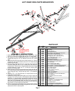
2. Mount the lock pin brackets (#6) to the boom carrier (#7) using four
1/2" x 1-1/4" bolts (#8) and four 1/2" locknuts (#9) make sure these
bolts are inserted in the right direction as shown above. Place the
lock pin (#14) & roll pin (#13) through the brackets (#6). Insert the
lock spring (#12) and 7/16" flatwasher (#11) to the inside of the lock
pin bracket and push the pin (#14) through. Secure the lock pin
assembly with cotter pin (#10) between the washer and bracket.
Make sure pin moves in and out freely and rotates down into the
"latch out" position easily.
3. Before mounting the boom carrier to the main frame assembly,
mount the UHMW wear pads (#16) to the boom carrier (#7) and
boom carrier brackets (#15) using sixteen 1/4" x 1" flathead screws
(#17) and sixteen 1/4" nuts (#18).
4. Now place the boom carrier (#7) on to the main frame assembly
(#1) so that the lock pins are in the holes of the main frame. Loosely
mount the boom carrier brackets (#15) to the boom carrier (#7)
using eight 3/8" x 1-1/4" bolts (#2), six 3/8" x 1-1/2" bolts (#19),
fourteen 3/8" flatwashers (#3) and fourteen 3/8" locknuts (#5).
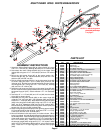
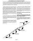
5. Attach the two top pulley mounts (#23) to the main frame (#1) as
shown using four 3/8" x 1-1/2" bolts (#2) and four 3/8" locknuts (#5).
Attach the top pulley (#27), spacer (#26) and cable retainer bracket
(#25) with 1/2" x 1-3/4" bolt (#24) and 1/2" locknut (#9). Assemble
the pulley on the top left side of the height adjuster main frame.
Adjust cable retainer brackets (#25) to always keep the cable in the
pulley grove even when there is no tension on the cable.
6. Attach the bottom pulley mount (#28) to the center of the boom
carrier (#7) using two 3/8" x 2-1/2" sq. U-bolts (#29) and two 3/8"
locknuts (#5). Attach the pulley (#27) to the bottom pulley mount
(#28) ear, using one 1/2" x 1-3/4" bolt (#24), cable retainer bracket
(#25), and spacer (#26), then secure with a 1/2" locknut (#9). Align
this bracket so the cable runs straight down from the top, around
the bottom pulley and back up to the rapidlink (#30).
ASSEMBLY INSTRUCTIONS
Page 3