


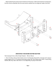
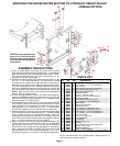
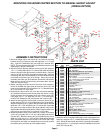
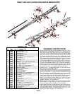
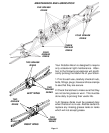

LEFT INNER WING PARTS BREAKDOWN
1. Attach the upper offset linkage (#6) to center section (#1) using
one 1/2" x 2" bolt (#7), bushing (#8) and one 1/2" locknut (#9).
2. Next attach the lower linkage bracket (#10) to the upper offset
linkage (#6) using one 1/2" x 2" bolts (#7) and one 1/2" locknut
(#9).
3. Mount the left center hinge (#2) to the center section (#1). Secure
with pin (#3), 3/4" machine washer (#16), 3/8" x 3/4" setscrew (#5)
and 3/8" jam nut (#4).
4. Bolt the linkage mounting plate (#11) to the left center hinge (#2)
as shown using two 3/8" x 2-1/2" U-bolts (#12) and four 3/8"
locknuts (#13). Bolt the lower linkage bracket (#10) to the linkage
mounting plate (#11) using one 1/2" x 2" bolt (#7), bushing (#8),
and one 1/2" locknut (#9).
5. Attach the left inner wing (#14) to the left center hinge (#2) with the
3/4" machine washer (#16) between the wing and hinge, using the
center hinge pin (#15). Secure with two 5/16" x 1/2" setscrews
(#17).
6. Insert the 1/2" x 1-1/2" bolt (#18) and 1/2" nut (#19) into the center
hinge (#2) as shown above.
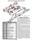
7. Assemble the wing latch handle (#20) to the center hinge (#2)
using the 7/16" clevis pin (#21), 3/8" flatwasher (#22) and secure
with 5/32" x 1" cotter pin (#23). Next attach the wing latch channel
(#24) to the wing latch handle (#20) using one 5/16" x 2-1/2" bolt
(#25), two 5/16" flatwashers (#26), and one 5/16" locknut (#27).
Next screw the tee bolt (#28) into the wing latch channel (#24) and
secure with 1/2" jam nut (#19) on back side.
8. Bolt the wing storage bracket (#30) to the left wing approximately
23" from latch plate on the left wing, using two 5/16" x 2" sq. U-bolt
(#35) and four 5/16" locknuts (#27).
ASSEMBLY INSTRUCTIONS
Page 5
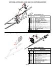
REF. PART
NO. NO. QTY. DESCRIPTION
PARTS LIST
Please order replacement parts by PART NO. and DESCRIPTION.
1. 03314 1 Center Section
2. 03315 1 Left Hinge
3. 03319 1 Center Hinge Pin
4. 04886 1 3/8"-16UNC Jam Nut
5. 00095 1 3/8"-16UNC x 3/4" Square Head Setscrew
6. 00171 1 Upper Offset Linkage Bracket
7. 01253 3 1/2"-13UNC x 2" Hex Head Bolt Gr.5
8. 02491 2 Bushing (3/4" O.D. x 1/2" I.D. x 1/2" lg.)
9. 02178 3 1/2"-13UNC Nylon Insert Locknut
10. 00170 1 Lower Linkage Bracket
11. 03318 1 Linkage Mounting Plate
12. 05294 2 3/8"-16UNC x 2-1/8" Square U-bolt
13. 02592 4 3/8"-16UNC Nylon Insert Locknut
14. 03322 1 Left Inner Wing
15. 03321 1 Inner Hinge Pin (3/4" x 20")
16. 02534 3 3/4" x 14 Ga. Machine Washer
17. 00091 2 5/16"-18UNC x 1/2" Square Head Set Screw
18. 01254 1 1/2"-13UNC x 1-1/2" Hex Head Bolt Gr.5
19. 00640 2 1/2"-13UNC Jam Nut
20. 05309 1 Wing Latch Handle
21. 00080 1 7/16" x 1-1/4" lg. Clevis Pin
22. 00059 1 3/8" Flatwasher
23. 00185 1 5/32" x 1" lg. Cotter Pin
24. 05310 1 Wing Latch Channel
25. 04221 1 5/16"-18UNC x 2-1/2" Hex Head Bolt Gr.5
26. 00004 2 5/16" Flatwasher
27. 02802 3 5/16"-18UNC Nylon Insert Locknut
28. 03320 1 Latch Bolt
29. 04642 4 Zerk
30. 03335 1 Storage Bracket
31. 04822 3 1/4"-20UNC x 1-1/16" Square U-bolt
32. 00199 1 3/8" Dia. x 3-1/2" lg. Lock Pin
33. 00182 1 1/8" Small Hair Pin
34. 02772 6 1/4"-20UNC Nylon Insert Locknut
35. 00909 1 5/16"-18UNC x 1-1/4" Square U-bolt
36. 03537 1 Gusset Plate
NOTE: To attach the gusset
plate (#36) follow step
7 on page 7.
15
28
24
19
25
27
21
20
22
26
26
23
14
12
7
10
9
7
5
4
16
16
29
3
17
29
16
19
18
29
11
8
13
1
8
7
9
6
9
32
33
27
30
31
36
35
33
27
34
2
17