


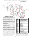
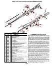

CENTER SECTION BOOM CARRIER BREAKDOWN
5
15
19
21
16
16
17
14
10
12
8
6
10
5
5
2
20
19
22
21
13
9
23
20
30
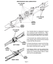
Note: This bracket must be 5" off center
in either direction.
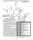
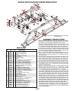
ASSEMBLY INSTRUCTIONS
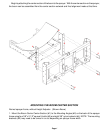
1. Begin by referring to the boom carrier (#1) mounting to the sprayer
frame (page 1) or mounting to the height adjust (pages 2 & 3). After the
boom carrier is mounted begin assembling the center section.
2. Mount the left floater tube (#2) to the boom carrier (#1) using one 1/2"
x 5" bolt (#11), pivot bushing (#5), and one 1/2" locknut (#10). Next
mount the right floater tube (#3) to the boom carrier (#1) using one 1/
2" x 5" bolt (#11), one pivot bushing (#5), and one 1/2" locknut (#10).
3. Place the auto-level springs (#4) between the left and right floater (#2
& 3) and the boom carrier (#1). Attach the left floater (#2) and right
floater (#3) using two linkage plates (#6), two pivot bushings (#5), two
1/2" x 4-1/2" bolts (#9), and two 1/2" locknuts (#10).
4. Now mount the shock (#8) to the right floater (#3) using one 1/2" x 5"
bolt (#11) and one 1/2" locknut (#10). Mount the opposite end of the
shock to the boom carrier (#1) using one 1/2" x 3" bolt (#12) and one
1/2" locknut (#10).
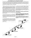
5. Mount the auto-level linkage (#7) to the left floater (#2) using one 1/2"
x 4-1/2" bolt (#9), one pivot bushing (#5), and one 1/2" locknut (#10).
NOTE: Make sure the arrows on the linkage are up as shown above.
Mount the auto-level linkage (#7) to the right floater (#3) using one 1/
2" x 4-1/2" bolt (#9), one pivot bushing (#5), and one 1/2" locknut (#10).
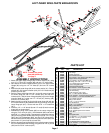
6. Mount the center section onto the boom center section (#22). Secure
the linkages (#7) on the right and left to the bottom of the boom center
section (#22) using two 1/2" x 4-1/2" bolts (#9), two pivot bushings (#5)
and two 1/2" locknuts (#10).
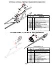
7. Attach the left and right auto-level sway control brackets (#13 & 14) to
the boom carrier (#1) using six 3/8" x 1-1/4" bolts (#19), six 3/8"
flatwashers (#20) and six 3/8" locknuts (#21). Next mount the UHMW
wear pads (#15) to the sway control brackets (#13 & 14) using four 1/
4" x 1" slotted flat head screws (#16) and four 1/4" locknuts (#17).
Assemble the UHMW wear pads (#15) to the auto-level sway control
guides (#23) and the bottom center support bracket (#34) using eight
1/4" x 3/4" slotted flat head screws (#18). Mount the sway control
guides (#23) with UHMW wear pads to the right and left sway control
brackets (#13 & 14) using two 3/8" x 1-1/4" bolts (#19), two 3/8"
flatwashers (#20) and two 3/8" locknuts (#21). Bolt the top of the sway
control guides and sway control brackets together using two 1/2" x 4-
1/2" bolts (#9), two springs (#24) and two 1/2" locknuts (#10). Mount
the bottom center support bracket (#34), with UHMW, to bottom tube
of boom carrier (#1) using four 3/8" x 2-1/2" square u-bolts (#30), eight
3/8" flatwashers (#20) and eight 3/8" nylon insert locknuts (#21).
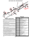
8. Assemble the center boom nozzle mounting plates (#29) to the center
section (#22) as shown using three 3/8" x 2-1/2" sq. U-bolts (#30) and
six 3/8" locknuts (#21). Next mount the center nozzle tube (#32) to the
mounting plates (#29) using three 5/16" x 1-1/2" sq. U-bolts (#31) and
six 5/16" locknuts (#33).
Please order replacement parts by PART NO. and DESCRIPTION.
1
19
19
9
9
4
5
11
27
9
21
18
15
18
23
24
9
9
9
10
17
19
21
21
26
25
21
10
28
5
Page 4
21
20
34
10
30
21
15
20
20
10
10
15
10
3
5
11
6
10
20
20
15
7
9
10
31
33
29
10
11
18
4
32
5
5
REF. PART
NO. NO. QTY. DESCRIPTION
1. 03306 1 Boom Carrier
2. 03309 1 Boom Carrier Left Floater
3. 03310 1 Boom Carrier Right Floater
4. 03330 2 Spring
5. 03313 8 Pivot Bushing (2-7/8" long)
6. 03311 2 Linkage Plate
7. 03312 2 Auto-Level Linkage
8. 03331 1 Shock
9. 01338 8 1/2"-13UNC x 4-1/2" Hex Head Bolt Gr.5
10. 02178 14 1/2"-13UNC Nylon Insert Locknut
11. 01975 3 1/2"-13UNC x 5" Hex Head Bolt Gr.5
12. 04073 1 1/2"-13UNC x 3" Hex Head Bolt Gr.5
13. 03307 1 Left Auto-Level Sway Control Bracket
14. 03308 1 Right Auto-Level Sway Control Bracket
15. 03324 4 UHMW Wear Pad
16. 05732 4 1/4"-20UNC x 1" Slotted Flat Head
17. 02772 4 1/4"-20UNC Nylon Insert Locknut
18. 00516 4 1/4"-20UNC x 3/4" Slotted Flat Head
19. 00523 8 3/8"-16UNC x 1-1/4" Hex Head Bolt Gr.5
20. 00059 16 3/8" Flatwasher
21. 02592 23 3/8"-16UNC Nylon Insert Locknut
22. 03314 1 Center Section
23. 02945 2 Auto-Level Sway Guide
24. 01348 2 Spring (1" O.D. x 3" long)
25. 03317 1 Auto-Level Latch
26. 01903 1 3/8"-16UNC x 3-1/2" Hex Head Bolt Gr.5
27. 00199 1 Lock Pin (3/8" O.D. x 3-1/2" lg.)
28. 00182 1 1/8" Small Hair Pin
29. 03334 3 Center Nozzle Tube Mounting Plate
30. 01887 7 3/8"-16UNC x 2-1/2" Square U-bolt
31. 00909 3 5/16"-18UNC x 1-1/4" Sq. U-bolt
32. 03333 1 Center Nozzle Mounting Tube
33. 02802 6 5/16"-18UNC Nylon Insert Locknut
34. 03399 2 Bottom Center Support Bracket
PARTS LIST