


LTO
LTO
TM
10
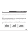
the subwoofer will be mounted in the trunk or rear firewall and will be the furthest speaker from the
listener/driver, so this will often be the 'zero reference'. If the subwoofer's sound enters the passenger
cabin via a vent, consider the mouth of the vent to be the zero reference point.
(2) measure the distance (in millimetres) from the midrange driver in the left front door to the driver's head.
(3) deduct the measurement calculated at (2) from the measurement calculated at (1) . The resulting figure
represents the distance by which the zero reference (let's suppose it is the subwoofer) is further from the
driver's head.
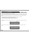
(4) Set the value to "mm" in the menu. From the menu, go to the output channel that feeds
the front left midrange driver. Now input the distance in millimetres calculated at [3]. The RM2 will convert
the distance to a time delay figure. The front left midrange driver will now be "virtually aligned" with the
subwoofer, measured at the driver's head.
When applied in this way to all speakers in the system (note: no delay should be added to the 'zero reference'
speaker), the result is an improvement in the apparent stage position, height, depth and the location and
focus of the performers on the 'virtual stage' that extends across the dashboard.
The final result will depend on several factors, including the accuracy of your measurements and the
directional characteristics and mounting angles of your speakers. As with most things in car audio, a lot of
experimentation is usually required to get the very best results. But that's what makes it such fun, right?!
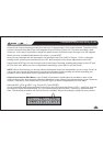
The UCS PRO has no analog input or output gain controls - gain adjustment is
handled entirely in the digital domain. The maximum signal level that can be handled by the A/D converters is
2.2V.
Select MODE . should show in the display. Press ENTER. Now you can set the level for Input
A (typically the left channel) in 0.5dB steps between 30.0dB and 6.0dB by adjusting the rotary control.
Press NEXT and repeat the procedure above for Input B (right channel).
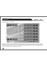
Units Utility Delay
Edit Input Gain
Input Gain (Edit Menu):
Parameter & Functions Set-up Guide