


2-302-30
2-302-30
2-30
Chapter 2: Hardware informationChapter 2: Hardware information
Chapter 2: Hardware informationChapter 2: Hardware information
Chapter 2: Hardware information
14.14.
14.14.
14.
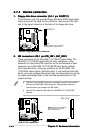
System panel connector (20-pin PANEL1)System panel connector (20-pin PANEL1)
System panel connector (20-pin PANEL1)System panel connector (20-pin PANEL1)
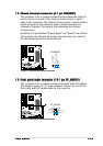
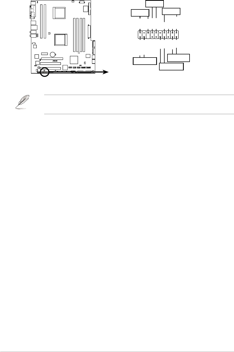
System panel connector (20-pin PANEL1)
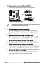
This connector supports several chassis-mounted functions.
•
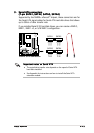
System power LED (Green 3-pin PLED)System power LED (Green 3-pin PLED)
System power LED (Green 3-pin PLED)System power LED (Green 3-pin PLED)
System power LED (Green 3-pin PLED)
This 3-pin connector is for the system power LED. Connect the
chassis power LED cable to this connector. The system power LED
lights up when you turn on the system power, and blinks when the
system is in sleep mode.
•
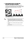
Hard disk drive activity (Red 2-pin HDD_LED)Hard disk drive activity (Red 2-pin HDD_LED)
Hard disk drive activity (Red 2-pin HDD_LED)Hard disk drive activity (Red 2-pin HDD_LED)
Hard disk drive activity (Red 2-pin HDD_LED)
This 2-pin connector is for the HDD Activity LED. Connect the HDD
Activity LED cable to this connector. The IDE LED lights up or flashes
when data is read from or written to the HDD.
•
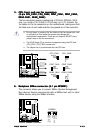
System warning speaker (Orange 4-pin SPKO)System warning speaker (Orange 4-pin SPKO)
System warning speaker (Orange 4-pin SPKO)System warning speaker (Orange 4-pin SPKO)
System warning speaker (Orange 4-pin SPKO)
This 4-pin connector is for the chassis-mounted system warning
speaker. The speaker allows you to hear system beeps and warnings.
•
Power/Soft-off button (Yellow 2-pin PWRSW)Power/Soft-off button (Yellow 2-pin PWRSW)
Power/Soft-off button (Yellow 2-pin PWRSW)Power/Soft-off button (Yellow 2-pin PWRSW)
Power/Soft-off button (Yellow 2-pin PWRSW)
This connector is for the system power button. Pressing the power
button turns the system ON or puts the system in SLEEP or SOFT-OFF
mode depending on the BIOS settings. Pressing the power switch for
more than four seconds while the system is ON turns the system OFF.
•
Reset button (Blue 2-pin RESET)Reset button (Blue 2-pin RESET)
Reset button (Blue 2-pin RESET)Reset button (Blue 2-pin RESET)
Reset button (Blue 2-pin RESET)
This 2-pin connector is for the chassis-mounted reset button for
system reboot without turning off the system power.
The system panel connector is color-coded for easy connection. Refer to
the connector description below for details.
K8N-DL
®
K8N-DL System panel connector
PANEL1
*
Requires an ATX power supply.
PLED-
PWR
+5V
Speaker
PLED
GND
RESET
GND
Reset
Ground
Ground
PLED+
HD_LED-
HD_LED+
HD_LED
SPKO
PWRSW
MLED+
MLED-
MLED