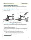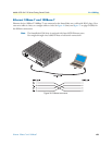
SmartNode Series VoIP routers overview 21
Model 4520 & 4110 Series Getting Started Guide 1 • General information
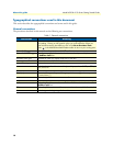
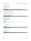
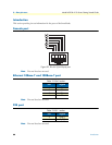
Ports descriptions
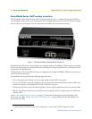
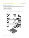
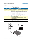
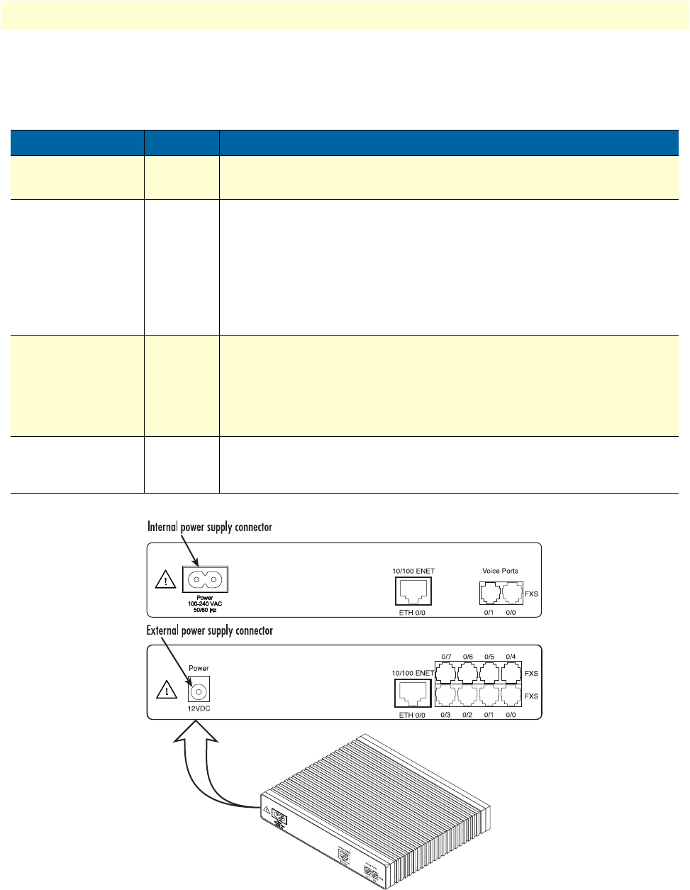
The SmartNode 4110 Series rear panel ports are described in table 4.
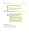
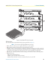
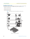
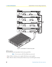
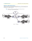
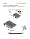
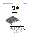
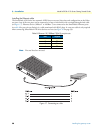
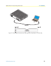
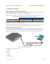
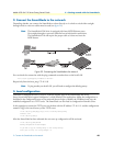
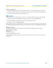
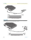
Figure 6. SmartNode 4110 Series power input connectors
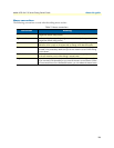
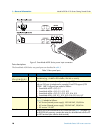
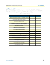
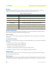
Table 4. Rear panel ports
Port Location Description
10/100 Ethernet
ETH 0/0
Rear panel
RJ-45 connector (see figure 5 on page 20) that connects the router to an
Ethernet device (a cable or DSL modem, LAN hub or switch, for example).
Voice Ports, FXS Rear panel
FXS RJ-11/12 connectors (see figure 5 on page 20) that connect the router
with an FXO port (a telephone for example). EuroPOTS support (ETSI
EG201 188). Configured per model as follows:
• Model 4112—0/0, 0/1
• Model 4114—0/0, 0/1, 0/2, 0/3
• Model 4116—0/0, 0/1, 0/2, 0/3, 0/4, 0/5
• Model 4118—0/0, 0/1, 0/2, 0/3, 0/4, 0/5, 0/6, 0/7
Power Rear panel The gateway is available in a DC or AC power input version (see
figure 6), labeled as follows:
• AC version (Internal power supply): 100–240 VAC, 50/60 Hz
• AC version (External power supply): 100–240 VAC, 50/60 Hz
• DC version: 12 VDC
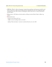
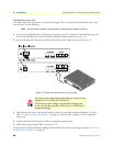
Console Front panel
Used for service and maintenance, the Console port (see figure 7 on page 22),
an RS-232 RJ-45 connector, connects the router to a serial terminal such as a PC
or ASCII terminal (also called a dumb terminal).