


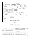

VA300 Vocal Master
OPERATING INSTRUCTIONS
General Operating Instructions:
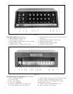
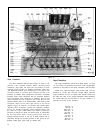
1. Set all front panel controls in the following manner: All
switches (1), (4). (7). set to “Out” position; “Reverb
Intensity” Control (2). and all “Volume” Controls (5)
and (8), set at “0”; all “Treble” and “Bass” Controls
(3) and (6). set in the “flat response” position
(indicator ribs at 12:00 o’clock); “On-Off-On” Switch
(10) set in the “Off” position.
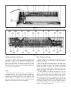
2. Unwrap the A.C. Line cord (12) from the storage
spindles (11); plug line cord into a 110 to 130 volt, 60
Hz. outlet. The line cord is a 2.75m (9 ft), 3-conductor
cord with a 3-pin grounding plug. If extension cords are
required, use a high quality, rubber-jacketed cable with
#18 gauge wire or larger.
3. Remove the speaker cables from the storage compart-
ments in the VA300-S Speaker Columns. Insert and lock
the right angle phone plug on the cable into either of
the two parallel-wired phone jacks; one on each Speaker
Column. Connect the other end of each cable to the
jacks on the rear panel of the Console marked
“Speakers” (15). These plugs are provided with locking
rings to lock the plug to the jack. Each speaker cable is
15m (50 ft) in length and is made from heavy duty
2-conductor, #18 gauge unshielded cable. Since each
Speaker Column has a pair of parallel-wired input jacks,
an alternate speaker hook-up would be to connect a
speaker cable from the Console to one Speaker Column
and then connect a second cable from this Speaker
Column to the second Speaker Column. Either hook-up
will provide an 8 ohm load. If longer speaker cables are
required, see page 6.
4. Connect one or more high impedance microphones to
the Console at the connectors marked “Inputs” (22).
The VA300 is designed to operate with any high
quality dynamic or
ribbon-type high impedance
microphone. For low impedance microphones see page
10.
5. Set all six Input Attenuator Switches (21) on the rear
panel of the Console to “Mic.” These switches should
generally be set in the “Mic.” position when using high
impedance dynamic or ribbon microphones. See page
6 for a description of the switch function.
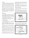
6. Turn on the Power Switch (10) located on the front
panel of the Console. Set the “Master Volume” Control
(8) to “5.” While talking or singing into one of the
microphones connected to the console, turn up the
individual volume control for that microphone to a
normal level. If at this point a slight hum is heard in the
speakers, switch the Power Switch (IO) to whichever
7.
8.
9.
10.
11.
“On” position results in the least amount of hum
coming from the speakers.
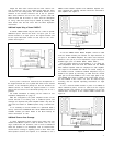
Now turn up the other Individual Channel Volume
Controls (5) which are being used. By use of the Indivi-
dual Channel Volume Controls (5), the microphones
may be balanced for level so that the sound coming
from the speakers is in proper balance for each micro-
phone. Increasing or decreasing the Volume on one
channel will have no effect on the other channels of the
Console.
Note the action of the Individual Treble and Bass Con-
trols (6); these controls are of the dual concentric type,
the large knob being the Bass control and the smaller
knob being the Treble control. Each of these knobs
incorporates an indicating rib. Under average condi-
tions, the controls should be set with indicating ribs
facing straight up (12:00 o’clock position) to provide a
normal “flat” frequency response. All Treble and Bass
Controls on the Console operate in the same manner;
turning the controls clockwise respectively increases
Bass or Treble, counterclockwise decreases Bass or
Treble. Note that changing the Bass or Treble Controls
on one channel has no effect on the other channels of
the unit.
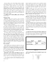
Turn the Reverb Intensity control (2) to a setting of
“4” Set the Master Reverb switch (4) to the “In”
position. Reverberation may now be selectively added
to any of the six channels by setting the Individual
Channel Reverb switches (7) to the “In” position. Note
that different settings of the Reverb Intensity Control
(2) will not effect the overall system gain. Generally a
setting of “1” to “4” of the Reverb Intensity Control
(2) is adequate for vocals. The Reverb Treble and Bass
Controls (3) operate in the same manner as those of the
individual channel Treble and Bass Controls but provide
independent tonal balance of the reverberant signal
only. These controls do not affect the tone of the
individual channels. For example, increasing Treble and
decreasing Bass will approximate the reverb sound of a
tape-type reverberation unit while decreasing Treble
and increasing Bass will approximate the sound of a
plate-type reverberation device.
Set all four Antifeedback switches (1) to the “Out”
position. These switches can help eliminate feedback.
Each switch cuts out part of the critical
feedback-generating frequencies. See page 8 for a
detailed description on how to effectively use them,
The Master Volume Control (8) will raise or lower the
volume of all channels simultaneously without affecting
the “balance,” or “mix.” NOTE: With the Console
driven at or near full power, pilot lamps will dim or vary
in brightness; this is a normal condition.
5