


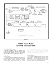
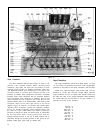
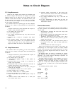
Notes to Circuit Diagram
D.C. Voltage Measurements:
Check the DC voltages first, because any deviation from
the nominal voltages will affect the AC voltage. In the power
amplifier section, Q31 to Q38, the key DC voltages are +94
(collector of Q33, Q35, and Q37). +22 (collector of Q31), and
the split voltage at the junction of R17, R19, R20, and R22.
If these three key DC voltages are correct, then proceed with
the AC voltage measurements.
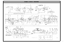
The numbers within the symbols on the circuit diagram
denote the D.C. voltage at that point with the following test
conditions:
1.
2.
3.
4.
5.
6.
Voltages measured at points indicated with respect to
chassis, unless otherwise indicated.
Line voltage 120v. 60 Hz (cps).
No input signal applied.
D.C. voltage measurements may vary ±20% from the
values shown.
Measured with a VTVM of 11-megohms input imped-
ance.
Q27 transistor voltages on the circuit diagram are with
the master reverb switch in the “IN” position. With the
master reverb switch in the “OUT” position, Q27 vol-
tages are: emitter 4.0, base 0.0, and collector 22.0
A.C. Voltage Measurements:
The numbers within the symbols on the circuit diagram
denote the A.C. voltage at that point with the following test
conditions:
1.
2.
3.
4.
5.
6.
7.
Voltages measured at points indicated with respect to
chassis, unless otherwise specified.
Line voltage 120v. 60 Hz (cps).
1,000 Hz signal applied to input, in “MIC” position, at
10 millivolts.
Measured with an A.C. VTVM of 1.0 megohms or
greater input impedance.
Noninductive load of 8 ohms, 200 watts connected to
speaker output jack for Q31 through Q38.
Echo input and output jacks to be open; echo gain
control set to maximum.
All antifeedback switches set to “OUT” position.
8. Reverb intensity set to minimum.
9. All tone controls set to 12 o’clock position.
10. All volume controls set to maximum.
11. Master reverb switch set to “OUT” position except as
noted.
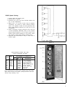
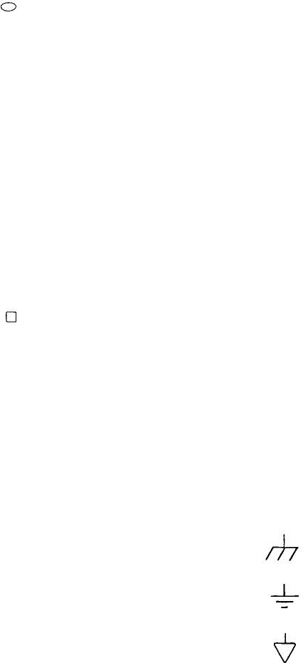
Chassis
Ground
Preamplifier
Ground
12. Individual channel reverb switches set to “OUT” pos-
Reverb
ition except where noted. Driver Ground
13. Transistor voltage measurements for Q20 through Q27
must be made with master reverb switch and individual
channel reverb switches in the “IN” position.
14. A.C. voltage measurements may vary ± 50% from the
values shown.
15. For A.C. measurements on Q25, Q26, and Q27, the
frequency may be varied ± 100 Hz. to obtain the A.C.
measurements shown.
Ohmmeter Measurements:
With the A.C. line cord unplugged and the power switch in
the “OFF” position, the following ohmmeter measurements
may be made.
1.
2.
3.
4.
5.
Reverberation Assembly M3 input and output coils
approximately 180 ohms.
Antifeedback Inductors M4 approximately 300 ohms.
B+ to ground approximately 50 ohms.
Ohmmeter plus probe to the junction of R17, R19,
R20, and R22, ohmmeter minus probe to ground:
greater than 100 ohms.
Ohmmeter plus probe to B+, ohmmeter minus probe to
the junction of R17, R19, R20, and R22: greater than
100 ohms.
6.
To test transistors and diodes, see page 15.
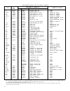
Shure part numbers are not shown in the parts list
accompanying the circuit diagram if parts are readily available
through local electronic parts supply distributors. In these
instances, the circuit diagram will show the values of the
standard parts.
All capacitor values are shown in microfarads. All nonelec-
trolytic capacitors are to be 100 volts or more unless otherwise
specified in the circuit diagram. Electrolytic capacitors are
shown in microfarads and volts.
All resistor values are shown in ohms. Resistors are all to be
10% tolerance unless specifically noted on the circuit diagram.
Resistors shown in the upper two lines of circuitry on the
diagram are ¼ watt unless otherwise specified. Resistors shown
in the lower line of circuitry are ½ watt unless otherwise
specified.
The following ground symbols denote:
20