


Set the controls on the second VA300 Console as follows:
Antifeedback Switches to “Out,” Master Reverb Switch
“Out,” Individual Volume Controls to “0,” and the Master
Volume to “5.” Adjust the Echo “Gain” Control to
approximately 1/3 rotation from the c.c.w. off position, and
use this control as a volume control to obtain the same
amplification level from both of the VA300 Consoles. Once
the Echo “Gain” Control is preset, the output of the second
VA300 Console will “follow” all control settings of the
original VA300 Console. Small changes in amplification level
on the second VA300 Console can be made by adjusting its
Master Volume Control.
An additional VA300 Console, PM300 or tape recorder can
be connected to the “To Tape Recorder” jack on the second
VA300 Console.
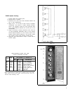
Microphone Cuing:
Microphone “cuing” may be preset by using the individual
Reverb “In-Out” switches to reduce the volume of, or turn off
an unused individual microphone channel. This is useful when
it is desired to preset the individual volume controls but only
have one or two microphones “live” at a time. This allows
tighter control of feedback, or additional control to avoid
pickup from off-stage microphones.
Insert an unwired phone plug into the Echo “To Output”
Jack. With the individual Reverb switch in the “In” position,
the channel will operate normally. In the “Out” position, the
channel level is reduced or turned off. The level of the “Out”
or “Cued” channel is controlled by the “Echo Gain” control;
turning this control fully counterclockwise turns off the
“Cued” channel. Returning the individual Reverb “In-Out”
switches to “In” restores the channel to the normal level.
For remote “Cuing” on and off, plug a foot switch into the
Echo “To Output” Jack on the VA300 Console. Turn the
“Echo Gain” control fully clockwise. With the foot switch in
the “On” position, the channels will operate normally. With
the foot switch “Off” those channels switched to individual
Reverb “Out” are turned completely off. This is useful for
remotely turning on and off preselected channels (Micro-
phones). The cable used with the foot switch should be limited
to 15m (50 ft) of low capacitance, single conductor, shielded
type (such as Belden #8401, #8410, #8411) to avoid high
frequency signal loss and to reduce the possibility of hum
pickup in the cables.
Stereo Operation:*
Stereo operation may obviously be obtained by using two
VA300 systems without any interconnections. If it is desired
to have one of the microphones connected to both systems,
simply use a “Y” connector on that microphone and feed its
signal to one Input on each Console. For making stereo tapes,
the “To Tape Recorder” jacks, one on each console, may now
be connected to the left and right Auxiliary Inputs, respec-
tively, on a stereo tape recorder.
Alternatively, stereo may be accomplished by using one
VA300 system and one PM300 with additional speakers. A
connection is made from the VA300 jack marked Echo “To
Input” to an input of the PM300. Those input channels of the
Console which are to be reproduced through the VA300
* As a general rule stereo sound reinforcement of this type
is quite annoying to listen to and is recommended only for
special effects.
12
Console speakers will require that the individual channel
Reverb “ln-Out” switches be in the “In” position. The channels
on which the switches are in the “Out” position will be heard
at the speakers connected to the PM300. This may be used for
a special echo effect, like “throwing” a voice from the rear of
the room.
Stereo recordings may also be made using one VA300
Console and one PM300. One channel of the stereo tape
recorder would be fed from the Console jack marked “To
Tape Recorder;” the other channel would be fed from the
open input jack of the PM300. NOTE: Reverberation can be
added to only those channels that are being reproduced by the
speakers connected to the VA300 Console.
A very convenient way of recording with a stereo tape re-
corder is to record the vocals on one tape channel and the
instruments on the other tape channel. Connect the VA300
“To Tape Recorder” jack to the right channel auxiliary input
of the tape recorder. A separate microphone is connected to
the left channel microphone input of the tape recorder; an
omnidirectional microphone suspended from the ceiling is
recommended.
A stereo phonograph may be connected for stereo operation
with either of the two above systems. Connect the left phono
output to one Input, and the right phono output to a second
Input. Refer to the section on Phonographs on page 10, for
Input arrangements. Set the individual Reverb In-Out switches
on these two channels to direct the sound to the left and right
speakers.
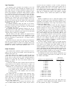
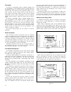
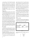
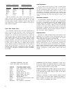
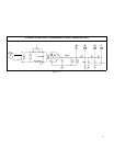
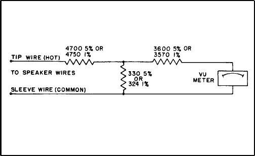
Connecting a VU Meter:
An external VU meter may be connected in parallel across
the speaker wires of the VA300 with a resistor attenuator, as
shown below. Use a true VU meter (such as Simpson Model
No. 1349) and three resistors connected as shown. The resis-
tors should be ½-watt carbon 5%, or 1% if available.
Figure 10
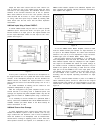
With an 8-ohm speaker load (two VA300-S) zero VU is 50
watts. Output power for other VU readings is shown in the
table below.
VU
Power to 8-ohm load
+3 100 watts
0 50 watts
-3 25 watts
-7 10 watts
-10 5 watts