


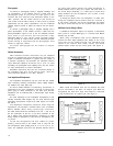
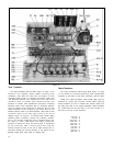
Driver Transistors:
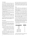
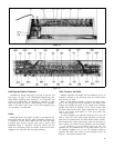
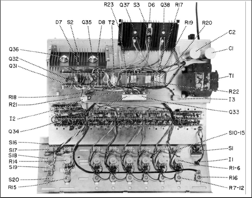
Figure 12
Output Transistors:
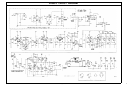
The driver transistors Q33 and Q34, Figure 12, Page 14 are
located on the amplifier chassis. Before removing these
transistors, write down the lead color and location at each
transistor solder junction. If replacing transistors, apply type
120 Wakefield thermal joint compound to each side of the
insulation wafer to provide good thermal transfer from
transistor to chassis. After replacement and before connecting
transistor leads, check transistors with an ohmmeter between
case and chassis; there should be no continuity. Be sure that
these transistors are not inverted in the circuit; they are not
identical devices. Q33 is an NPN transistor, while Q34 is PNP
transistor. Refer to the lower right corner of the circuit
diagram, Figure 18, Page 21, for terminal code. NOTE: When
replacing driver transistors, perform the following modifica-
tion (if not already performed): place insulated tubing over
the leads of a 3.3k, 1/2W resistor and solder it across the
terminals to which the white and black leads of transformer
T2 are connected. Add a second ground wire from the
terminal nearest the front of the unit to which resistor R21 is
connected, through the chassis grommet, to the ground on the
Speaker Output jacks (same path as existing wire).
The output transistors Q35 through Q38, Figure 12, Page
14 are located on the black finned heat sinks. Replacement
procedure is the same for the driver transistors, Q33 and Q34.
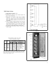
NOTE: The output transistors, Q35 through Q38, must be
matched for current gain and part number. When replacing
output transistors be sure to replace with devices which have
the same gain code as the original transistors. Shure transistors
are coded either by the last letter in the part number or a
color-dot on the top of the transistor.
Blue Dot = A
Red Dot = B
Orange Dot = C
Yellow Dot = D
Green Dot = E
Brown Dot = F
Pink Dot = G
Violet Dot = H
Black Dot = J
White Dot = K
14