


f
r
r
is
indicated
onthe
TV
screen;
if there
is
no
trouble,
the
cartridge
sets upa
test
for
the
two
keyboards.
NOTE:
The
Test
Cartridge
requires
substitution
ofthe
power
unit
during
test.
Use
the
special
500mA
power
unit
(see
Parts
List)
instead
of
the
original
power
unit.
1.
Press
and
hold
"Clear"
button
on
Studio
II
console.
In-
sert
Tester
I
cartridge
into
slot
while
holding
"Clear"
button.
NOTE:
Insert
cartridge
into
console
with
label
side
toward
"Clear"
button.
Follow
label
directions
concerning
removal
of
conductive
rubber
strip
covering
the
plug.
2.
Release
"Clear"
button.
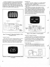
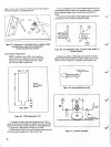
A
pattern
similarto
that
of
Fig.
9a
appears
on
screen
immediately,
and
Tester
I
beginsits
scan
of
the
system
(indicated
by
the
black
streak
moving
through
the
white
field in
the
lower
half
of
the
pattern).
If the
pattern
fails to
appear
or a
pattern
other
than
that
shown
appears,
a
faulty
chip
is
indicated.
Replace
PC
board.
In
about
11
seconds,
the
first
scan
is
complete.
The
display
shifts
to
the
pattern
shown
in Fig.
9b
with a
white
streak
scanninga
black
field.
This
scan
takes
another
1
1
seconds.
At
theend
of
the
second
scan,
the
system
changes
the
pattern
on
the
lower
halftoa
series
of
transient
vertical
white
lines
on
black
and
then a
series
of
black
lines
on
white.
This
sequence
takes
about
2
seconds.
At
the
end
of
this
short
sequence,
the
pattern
again
shifts-to
that
illustrated
in
Fig.
9c.
This
indi-
cates
all
memories
operational.
A
digit
or
digits
appearing
in
the
"checkerboard"
pattern
in
the
center
of
the
screen,as
shown
in
Fig. 9e,
indicates
chip
failure
in
the
PC
board
and
the
board
mustbe
replaced.
If the
checkerboard
appears
as
in
Fig.
9c,
touch
the
keys
-
oneat a
time
-
of
Keyboard
A,and
then
Keyboard
B.
As
each
key
switch
closes,
the
digit
on
screen
should
change
to
a
checkerboard
square.
(If any
digit
remains
on
screen
after
key
actuation,
the
keyboard
is
defective
and
must
be
replaced
(see
Page
11).
When
all key
closures
are
complete
(indicating
CATV
CO-AX
CATV
MATCHER
STUDIO
II
SELECTOR
SWITCH
BOX
ANTENNA
TERMINALS
TV
RECEIVER
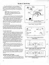
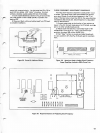
Figure
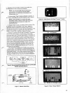
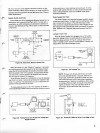
6.
Selector
Switch
Box
Connects
Between
CATV
Cable
Matcher
and
Home
Receiver
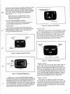
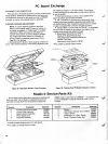
ANTENNA
TERMINALS
£1
nc/i
TV
-«
»-STUDIOII
o
-T®~L
STICKY
TAPE
TO
CONSOLE
Figure
8. Adjust
Receiver
for
Sharp
"Freeway"
Display
(d)
Operable
Keyboardsand
Electronics
mmmm^m
(e)
Bad
Key
A7and
Digital
Failure
Figure
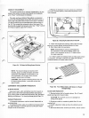
7. Selector
Switch
Box
Figure
9.
Tester 1
Screen
Patterns