


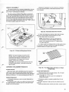
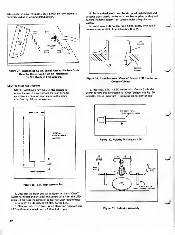
cable in slot in cover
(Fig.
27).
Shield
must
be
fully seated to
minimize radiation ofmodulated
carrier.
4.
From
underside
ofcover,
bend
clipped
pigtails
backand
collapse
black
plastic holder
with
needlenose
pliers
or
diagonal
cutters.
Remove
holder
from
console
holes
using
pliers
or
cutter.
5.
Install new
LED
holder.
Press holder
gently
into
hole in
console
cover
until itclicks
into
place
(Fig.
29).
sJ
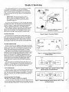
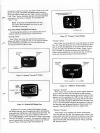
Figure 27.
Disconnect
Co-Ax
Shield
First to
Replace
Cable.
Resolder
Center
Lead First
on
Installation.
Do
Not
Overheat
Foil in
Board.
LED indicator
Replacement
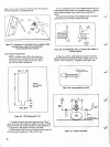
NOTE:
Installing a
new LED in the
console re-
quires
the
use
ofa
special tool that
can be
fabri-
cated
from
a
piece
ofsheet
metal witha
sabre
saw.
See
Fig. 28for
dimensions.
*
J
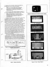
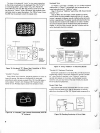
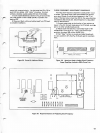
Figure 29.
Cross-Sectional
View
of Seated
LED
Holder in
Console
Cabinet
6.
Placenew
LED in
LED holderwith
shorter
(cathode)
pigtail towardside
connectedto "Clear"
switch (see
Fig. 30
and31
). Thisis
important
—
indicator
cannot
light if con-
I
*m
5.75-
M
I
2
O
3
z
2
I
I
I
0.26"
MATERIAL:
0.050
'ALUMINUM
OR
STEEL
CATHODE
(-)
PIGTAIL
SHORTER
THAN ANODE
d
-
/
+
j
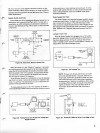
Figure 30. Polarity
Marking
on
LED
-»»j
o.2rj-«-
T
Figure
28.
LED
Replacement
Tool
1 . Unsolderthe
blackand whiteleadwires
from"Clear"
switch terminals
and
unsolder
the
yellowwire fromthe
LED
pigtail.
This
frees
theconsole top
halffor LED
replacement.
2. Snip both
LED pigtailsoffcloseto
the LED.
3. Placeconsole
cover,face
up,
on
block
and
driveoutold
LED
withsmall screwdriver or
1/8-inch driftpin.
-.
+
!
f¥
>
T>
<r_
/
YELLOW
WIRE
* n
PLASTIC PILLAR
(PART
OF
CONSOLE
CABINET)
^
,>
Figure
31. Indicator
Assembly
12