


r
r
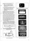
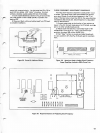
POWER
SUPPLY
UNIT
18 FOOT
CONSOLE
CORD
TV/STUDIO
II
SELECTOR
SWITCH
KEYBOARD
A
ON/OFF
INDICATOR LIGHT
STUDIO II CONSOLE
CLEAR
BUTTON
KEYBOARD
B
CHANNEL
2/CHANNEL
3
SWITCH
SOUND
ON/OFF
SWITCH
(UNDER
CONSOLE)
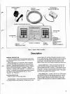
Figure 1.
Studio
II Major
Assemblies
Description
GENERAL
DESCRIPTION
Studio
II
is
a
sophisticated,
microprocessor-based
system
for
home
entertainment
usinga
broadcast
TV
receiver
asthe
display
device.
Heart
of
the
Studio
II is
a
solid-state,
40-pin
integrated
circuit
microprocessor
that
functions
as a
micro-miniature
computer.
It
provides
central
computer
control
fora great
variety
of
educational
and
entertainment
programs.
Program
memory for
five
built-in
games
-
"Doodles",
"Patterns",
"Bowling",
"Freeway",
and
"Addition"
—
isincluded
in the
console. A
receptacle
in the
console
accepts
plug-in program
cartridges for
many
additional
games
such
as
"Tennis",
"Baseball"
and
"Blackjack".
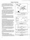
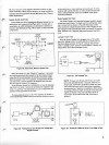
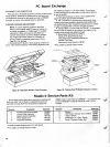
SYSTEM
DESCRIPTION
Studio
II consistsof
three
major
pieces:
Control
Console
—
Houses
the
keyboardsand
all
electronics
for
program
selection
and
processing.
All electronics
in the
console
(digital,
RFoscillator/modulator andaudiocircuits)
are
on
a
single PC
board. Signal informationfrom theconsole
is
transferredto
the SelectorSwitch
Unitthrough
a
single
coaxial
cable.
This
same
cablecarries DCpower fromthe
SelectorSwitch
Unit
to
theconsole tooperate the
electronics.
Selector
Switch Unit
—
Forms
the
interface between the
Control
Console,
the Studio II Power Supply Unit,the TV
receiving
antennaand
the
TV
receiver.
A
two-positionswitch
allows
theTV
receiver
to
beconnected conveniently
to
either
the Studio
II orto
thereceiver's antenna system. Thisswitch
also
servesas the
game'son/offswitch.
Power
Supply Unit
-
A
sealed, 120
VACto9 VDC
adapter
with
a
6-foot (1
.8m)cord and
plugthat connects
toa
minia-
ture
(3mm)
phonejack
onthe
Switch Selector
Unit. The
9
VDC
iscoupled to
thegame's 18-foot (5.5m) coaxialcable
through an
RF-filteringcircuit housed in the SelectorSwitch
Unit.
r