


Studio
II
Servicing
The recommended
Studio
II service procedure
istodeter-
mine
whetherthe problem
is in oneof
the periphery
components,the
interconnecting
cablesor in
theconsole
itself.
If
the
PCboard in
theconsole
isfound
to
be
faulty,
it
must
be
returned to
RCAfor
repairon an
exchange
basis.
See Page 14.
IMPORTANT: No
attemptshould be
madeto
adjust
orrepair an
inoperative PC
board
—with
the
exceptionof
the
clock-frequency
adjustment
described
on Page 13.
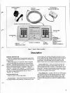
Asan
aid
to
servicing
Studio II,
a
test
cartridge (see
below)
is available
from RCA.
Thecartridge is not
essential to
service
Studio
II;however, it does
provide a
quickand
convenient
meansfor
isolating malfunctions
in thedigital
systems.
When
a
Studio II
comes in forservice,
itis
importantthat
you have
all threeassemblies:
SelectorSwitch Unit,
Power
Supply
Unitand Console.
If the complaint
involves
one or
more
plug-in cartridges,
these
should be
included aswell.
SYSTEM
CHECKING
Checking
Studio II
operation canbe done
quickly and
easily using
a
test
cartridge
available from
RCA (see
Page
15
forordering
information).
System
performance
can alsobe
checked by
operatingeach
built-in game
function;however,
this
proceduretakes more
timethan
thetest cartridge
check.
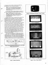
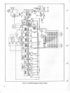
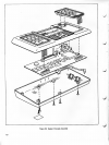
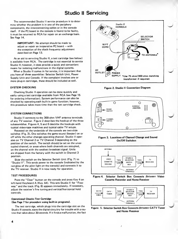
SYSTEMCONNECTIONS
Studio
II connects
to
the
300-ohm
VHF antenna
terminals
ofany TV
receiver. Figure 2
describesthe
hookupofthethree
subassemblies. Figures
4,
5
and 6descirbe
thehookups
with
typical
video-tape machinesand
typical
cable TVsetups.
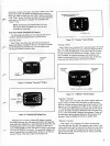
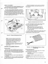
Recessed ontheunderside
ofthe
console aretwo
slide
switches
(Fig.
3).
One
switchesthe game
sound (beeper)
on or
off
whilethe otherchanges
operating
channel. Studio
II oper-
ates onTV
Channel 2or TV
Channel
3depending
on the
position oftheswitch.
Theswitch
should beset on
the unoc-
cupiedchannel;or
areaswhere
both
channelsare occupied,
on thechannelwith
theweakest
broadcast
signal. Units
are shipped
fromthe factory
with the
switch
in Channel 3
position.
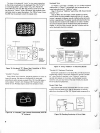
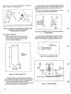
Slide the
switch on
the
Selector
Switch Unit
(Fig.
7)
to
"Studio 1
1".
This
sends powerto
theconsole
(indicated by
the
red
glowof the
pilot light
on
the
console) and
connects
itto
the TV
receiver. Studio
II is nowready
foroperation.
TEST
PROCEDURES
Pressthe
"Clear" button
on the
console and
press Key4 on
left-hand Keyboard
A (Key A4).
Thissets
Studio
II for "Free-
way"and
thetrack (Fig.
8)
appears
immediately.
If
necessary,
adjust
the receiver's
fine tuningand
vertical/horizontal
hold
controls.
Operational Checks
Test
Cartridge
(See
Page7
for
procedure
using
built-in programs).
Thetest
cartridge, which plugs
intothe
cartridge slot onthe
StudioII console,scans
the
digitalcircuitry
fortroublewith
a
rou-
tinethat
takesabout
30
seconds.
If itfindsa
malfunction,
thefact
SELECTOR
SWITCH
TO
ANTENNA
\0>
POWER
SUPPLY
*use
75ohm/300
ohm
matching
transformer
ifrequired.
sj
Figure 2.
Studio
II Connection
Diagram
^J
Figure
3. Locations
ofChannel Change
and
Sound
On/Off
Switches
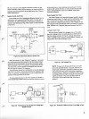
ANTENNA
I
VIDEO
CASSETTE
MACHINE
TWIN
.
STUDIOII
SELECTOR
SWITCH
BOX
TWIN
TV
RECEIVER
LEAD?
LEAD^
^
-^ ANTENNA
/
TERMINALS
sj
Figure4. Selector Switch Box
Connects
Between
Video
Cassette
Recorder
and
Home
Receiver
CO
-AX
TWIN
TWIN
CATV .
TUNER
STUDIOII
SELECTOR
SWITCH
BOX
TV
RECEIVER
CABLE
LEAD^
LEAo7
^
ANTENNA ,
TERMINALS
Figure 5.
SelectorSwitchBox
Connects
Between
CATVTuner
and Home
Receiver