


r
~
r
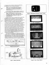
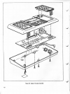
CONSOLE
DISASSEMBLY
Theconsole
consistsofsix
separate
subassemblies: thetwo
halvesof
the cabinet,
printedcircuit board, two
keyboards,
anda
"Clear"
switch/power-on indicator.
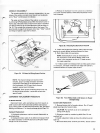
The upperand lower
halvesof
the
cabinetare
separated
by
removing
5Phillips-head screws.
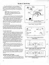
Withthe bottom
cover
re-
moved,the
underside
of
the printed
circuit board
is exposed.
Lift the
PC
board upatthe
cartridgesocket
side asshown
in
Fig. 24. This
exposes
the
componentsideofthe
board.The
board
standson
edge
if set
between pillar
(near "Clear"switch)
and flangeof
cabinet upper
half
as
shown.
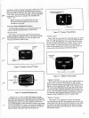
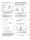
3. Release thekeyboard fromthe
console
by
unlatching
two
browncolored latchesas illustrated. Keyboard
is now
free
of
console.
CARTRIDGE
RODE
^
—
"***
^k^===^
'^A
x%
*
\$
"\°
S
V
/
^/^^^^^
"^-^
CART
X^Ss^^
SOCKET
]
\^^
SL0T
TOP
HALF
OF
CABINET
r*
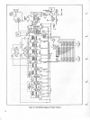
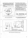
Figure
24. PCBoard in
Wiring
Access
Position
NOTE:
Thechannel-change
andsound
on/off
switches, plug-in cartridge
connectorand
other
components mounted
onthe PCboard
are not
field replaceable.
All PCboard
faults (except
speaker)
require board
exchange.
CAUTION:
Tunersprays containingsilicon
must
not
be usedon
slide switches.
Irrepairable switchdam-
agewill
result.
COMPONENT
REPLACEMENTPROCEDURE
PC Board Removal
Disconnect black,white and
yellowwiresfrom
board; un-
solder coaxial
cablefrom board
and
carefully
pull
out key-
board
ribbon
leadsfrom RC
board connectors.
See "PC Board
Packing
and
Shipment"for
boardexchange
details (Page 14).
Keyboard
Replacement
1.
Keyboard
replacement requiresconsoledisassembly as
describedabove.
2. Unplug
the ribboncable ofthe
defective
keyboardfrom
the
ribbonconnector onthe
PC
board by
pulling
the
ribbon
straightout
ofthe connector.
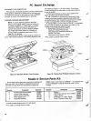
Figure25. Releasing
Keyboardfrom
Console
4. Install
newkeyboard
by
feeding
ribbon cablethrough
opening in consolebefore
latching keyboardin place.
5. Push
ribboncable into connector.
NOTE: Some Studio II units
use
unenclosed
rib-
bon
connectorson PC board. Ribbon
cablemust
center in the
connector
sothat
all 1
1
leadscontact
for proper
operation.
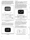
6. If ribbon
cablefrom keyboardfails
to
makegood contact
in connector,trim back
1/16
inch
fromedge with
ordinary
householdscissors
to
expose
fresh
contact.
Figure
26.
Trim Ribbon
Cable
with Scissors
to
Repair
Damaged
Edge
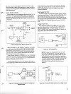
Coaxial
Cable Replacement
1 . Remove bottom
halfof console
cabinet.
Pryoff metal
shield covering
endof
coaxial cable.
CAUTION:
Pry
carefully so
as nottodamage foil
wiring
on
PC
board.
2. Disconnectcable
by
unsolderingshieldfirst.
Donot
overheat
foil.
3. Install replacement
cable asshown by solderingcenter
lead first.
4. Re-install
shield
cover carefully
andfirmly. Center coaxial
11