2-7
Installation
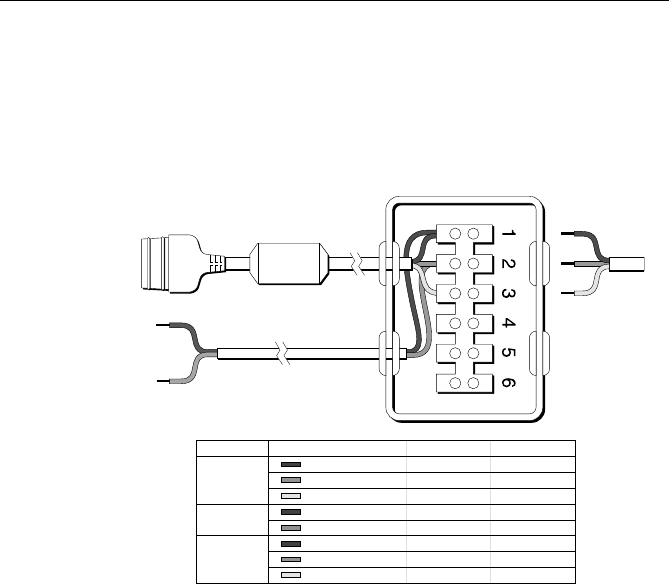
The junction box includes:
• SeaTalk cable and connector to attach to display unit
• Power cable to connect to 12 V power (if required)
• Input connections to connect SeaTalk cable from external equipment
• Spare connections for another instrument
The illustration below shows how to connect the junction box.
Core
Black (screen)
Red
Yellow
Black (screen)
Red
Black (screen)
Red
Yellow
To Ship’s
Power Supply
Spare
Input
Cable
SeaTalk
Power
GPS
Terminal
1
2
3
1
2
1
2
3
Function
0V
+12v
SeaTalk
0V
+12V
0V
+12V
SeaTalk
To GPS
Power Out: 1 & 2
Power In: 1 & 3
To Radio’s
SeaTalk
Socket
+VDC (fused)
0 VDC (return)
2.4.5 Antenna Connections
Your coaxial VHF antenna cable connects to the RAY230/E antenna cable
on the rear panel using a PL259 VHF type connector. Your VHF antenna
cable can be cut to length but the overall cable length can be critical to
performance. If you are uncertain, contact a professional installer or call
Raymarine Customer Service. If a longer cable length is required, RG-58
(50 ohm) coaxial cable or equivalent cable can be used for runs up to a
maximum of 50 feet. If the distance required is even greater, we recommend
using low loss RG-213 or equivalent cable for the entire run to avoid
excessive losses in power output.
If the antenna RF connector is likely to be exposed to the marine
environment, a protective coating of grease (Dow Corning DC-4 or similar)
can be applied to the connector before connecting it to the radio. Any
other extensions or adapters in the cable run should also be protected by
silicon grease and then wrapped with a waterproofing tape.
Figure 2-6 SeaTalk Junction Box Connections


