


C637M-B (10/03) 7
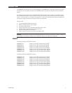
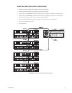
11. Up arrow/Quit button: Used in conjunction with the Controller and ENC buttons. Press to scroll through the information on
the LCD display, to move through each menu, or to go back to the previous menu.
12. Down arrow/Info button: Used in conjunction with the Controller and ENC buttons. Press to scroll through the information
on the LCD display or to move through each menu.
13. Select/C-F button: Use to enter the option you have selected or to change the temperature display from celsius to
fahrenheit.
14. Exit/Alarm reset button: Use to return to the previous menu or to stop an alarm.
15. Voltage warning LED: Illuminates red and an alarm sounds if the output DC voltage is under +5 V or over +12 V.
16. Over temp LED: Illuminates red and an alarm sounds if temperature irregularities occur.
17. Fan fail LED: Illuminates red and an alarm sounds when a fan’s rotation speed is lower than 1000 rpm.
18. Power fail LED: Illuminates red and an alarm sounds if a redundant power supply fails.
19. Power LED: Green when the power is on.
POWER 2 POWER 3
UPS MODEM
RESERVED
MONITOR
ᕥ
ᕢ ᕣᕡᕫᕾ
ᕧ
ᕦ
ᕨ
ᕩ
POWER 1
ᕤ
ᕫᕵ
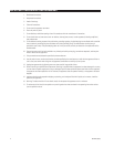
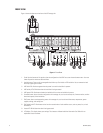
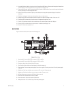
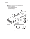
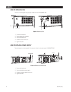
Figure 2. Back View
1. Host channel A: Has two 68-pin SCSI connectors for SCSI In and Out.
2. Host channel B: Has two 68-pin SCSI connectors for SCSI In and Out.
3. Terminators: Attach to Host Channel A and B Out ports.
4. Fans: Provide sufficient airflow and heat dispersion inside the storage unit.
5. Power supplies: There are three power supplies. Each one has a green LED and a power switch. The third power supply is
a backup.
6. Monitor port: Serial port that allows you to connect to a PC or terminal. Factory use only.
7. Modem port: Serial port that allows you to connect to a modem. Factory use only.
8. UPS port: Allows you to connect to a UPS device. Factory use only.
9. Power fault LED: Illuminates red if there is a problem.
10. Power reset switch: Press once to reset the power fault.
11. Main power switch: Turn on after turning on the three power supplies.
BACK VIEW
Figure 2 shows the features on the back of the IDE storage unit.