


11
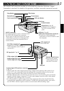
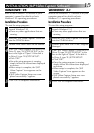
The controls and connectors marked
*
can be used only when the GR-DVM1 Digital
Camcorder is attached. For details of its operation, read the camcorder instruction manual.
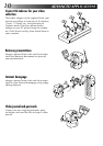
CONTROLS AND CONNECTORS
* MULTI connector
•The Docking Station can be connected with
the GR-DVM1 through this connector.
Never touch it with your hand or hit it with
a hard object; if the pins are damaged, the
connectors will become unusable due to
contact failure.
* DC output jack
•For dealer use.
* Stop button * Play button
* Rewind button * Pause button
* Fast forward button * Edit start button
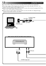
JLIP jack
੬ p. 13
(JLIP: Joint Level Interface Protocol)
•Connect to a JLIP-compatible
comcorder or VCR to control it from
the computer.
* Unlock button
* Lock lever
* Digital jack ੬ p. 13
•Connect to the computer’s
RS-232C terminal (COM
port).
* S2 (Video) output jack
•Outputs the S-VIDEO signal.
(Also compatible with S1 and S2
connectors.)
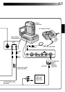
DC input jack ੬ p. 13
* Remote control sensor
•Receives the remote
control signals for the
attached Camcorder.
* Edit jack
Capture input (EXT.)/printer connector
੬ p. 13
•Connect with the video output (stored image output) of the optional video printer. Even
when a TV is not connected to the video printer, this connection allows you to see the
images output from the video printer on the LCD screen while printing.
•The date and timecode are not shown on the LCD screen. If you want to print out the date
together with the images, connect a TV to the video output connector of the video printer
and operate it by referring to the TV screen.
•It is also possible to capture images from video equipment other than the GR-DVM1by
connecting the equipment to this connector. To make this operation possible, also attach
the GR-DVM1 and set its power switch to record mode without loading a tape.
* Audio output jack (Right)
* Video output jack
* Audio output jack (Left)