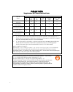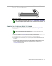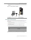
Connecting to the Network
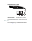
4-8 NAC Controller PEP Installation
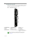
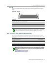
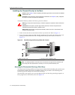
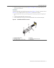
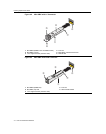
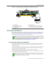
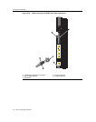
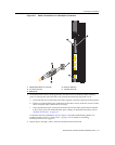
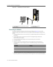
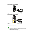
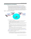
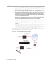
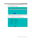
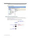
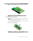
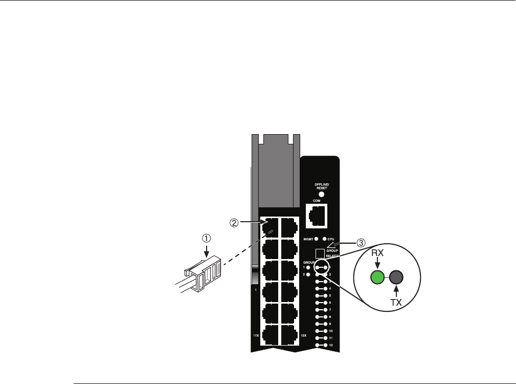
Figure 4‐5showsconnectingatwistedpairsegmenttothe2S4082‐25module.Itisassumedthat
thechassispoweristurnedontoprovidepowertothemodule.RefertoFigure 4‐5andproceedas
follows:
1. Ensurethatthedeviceconnectedtotheotherendofthesegmentispowered
ON.
2. ConnectthetwistedpairsegmenttothemodulebyinsertingtheRJ45connectoronthe
twistedpairsegmentintotheappropriateRJ45portconnector.
Figure 4-5 Connecting a Twisted Pair Segment to the NAC Controller PEP
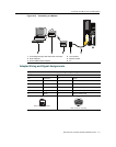
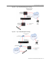
3. VerifythatalinkexistsbycheckingthattheportRX(Receive)LEDisON(flashingamber,
blinkinggreen,orsolidgreen).IftheRXLED
isOFFandtheTX(Transmit)LEDisnot
blinkingamber,performthefollowingstepsuntilitison:
a. Toviewthereceiveandtransmitactivityonagroupofsegments,presstheGROUP
SELECTbutton(seeFigure 4‐5)tosteptothegroupofinterest(Groups1and2).
Each
timetheGROUPSELECTbuttonispressed,theGROUPLEDlightsupinsequence,
indicatingwhichGroupisselected.Thereceiveandtransmitactivityforthatgroupof
segmentsisthenindicatedbytheRXandTXLEDsforeachsegment.
b. VerifythatthecablingbeingusedisCategory5
UTPwithanimped ancebetween85and
111 ohms. Fortheporttooperateat100or1000Mbps,Category 5cablingmustbeused
andinstalledproperly.
c. Verifythatthedeviceattheotherendofthetwistedpairsegmentisonandproperly
connectedtothesegment.
d. VerifythattheRJ45connectors
onthetwistedpairsegmenthavetheproperpinoutsand
checkthecableforcontinuity.Typically,acrossovercableisusedbetweenhubdevices.A
straight‐throughcableisusedtoconnectbetweenswitchesorhubdevicesandanend
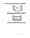
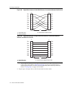
user(computer).RefertoFigure 4‐6andFigure 4‐7for
four‐wireRJ45connections.Refer
toFigure 4‐8and Figure 4‐9foreight‐wireRJ45connections.
1 RJ45 connector 2 RJ45 port connector (port 1) 3 GROUP SELECT button