10-10
Cisco TelePresence System 3200
OL-14521-01
Chapter 10 First-Time Setup
Setting Up CTS Components
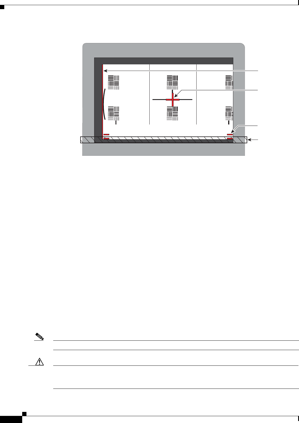
Figure 10-6 Correct Camera Target Alignment—Left Display
• Click Hide Camera Target to remove the alignment images.
• Click Done when you complete the adjustment.
Show All Camera Targets
• Click Show All Camera Targets to align each camera independent of the other cameras.
Flipping the Video Image
• Click Flip Video on Each Display to display a mirror image—meaning to simulate the image that
attendees will see—for the selected screen(s). Use this feature to make sure all three cameras are
vertically aligned.
Focus the Camera
• Place the small target on the table.
• Click Setup, then click Show Focus Target.
• Adjust the small target so that the green box encloses some of the patterns on the small target.
• Adjust the focus ring on the camera lens so the lines on the target are in focus. The ring is labeled
“N – 8”. The thumbscrew (or 0.9 mm Allen wrench) is used to unlock the focus ring.
• Click Hide Focus Targets, then click Done when you complete the adjustment.
Attaching the Camera Hood Assembly
• After you complete the camera adjustment, attach the camera hood assembly. See Figure 10-7.
Note Attach the top hood before attaching the bottom hood.
Caution Do not overtighten the screws, or use a power screwdriver to tighten the screws. In addition, make sure
that you use screws of the correct length (20 mm). Overtightening the screws, or using a screw that is
too long, can cause the plastic hoods to break.
Red plus
sign within
black cross
Red lines
Table
edge
Red
Vertical line
205766


