


18
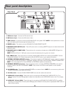
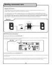
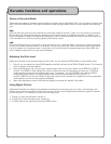
AM/FM Antenna Connection
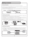
Connecting the FM Antenna to the GIG MAN PLUS
The FM antenna looks like a thin wire with a gray plastic plug at one end. To connect the FM antenna to the GIG MAN PLUS,
insert the gray plug into the FM antenna receptacle.
Connecting the AM Antenna to the GIG MAN PLUS
The AM antenna has a braided wire connected to a large oval shaped plastic antenna. The opposite end has two exposed cop-
per-colored wires.
To connect this antenna, press down the tabs on the AM antenna receptacle on the back of the GIG MAN PLUS. Now insert
the copper-colored wires into each side of the receptacle and then release the tabs to secure the wires in place.
Getting connected cont
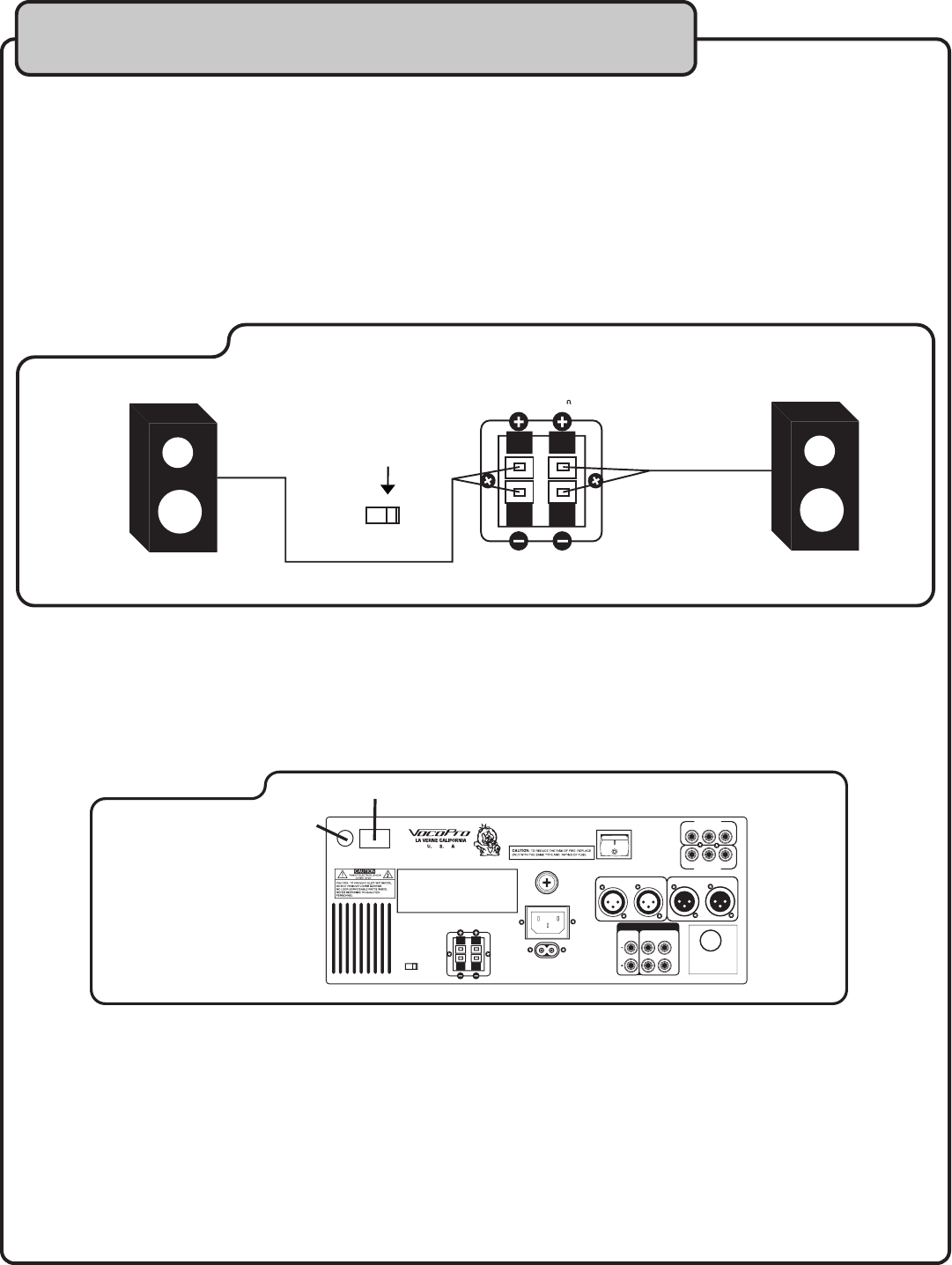
Speaker Connection
The GIG MAN PLUS has a set of speaker connectors for connection to external speakers. Remember that only
speakers with an impedance rating of 8 ohms should be connected.
To connect speakers, first unlock the plastic fasteners on each speaker connector by pushing downward on them.
Then strip approximately a 1 /2” (1.27cm) of insulation from the speaker wire ends and twist the strands so that they
can easily slide through the holes. Once a wire is inserted, lock them in place with the fasteners by pushing upward on
them. It is easy to over-insert a wire into a speaker connector so that the insulation is inserted as well. To ensure this
doesn’t happen, only insert the wires to the point where you can still see the edge of the insulation.
*Set to EXT for
External Speaker
Output
L
R
SPEAKER
8
INT EXT
Speacker Selector
Speakers
AM/FM
FM
AM
U
L
C
US
LISTED
www.vocopro.com
www.vocopro.com
VCD+CDG COMBO Model: GIGMAN PlUS
VOCOPRO
www.vocopro.com
Rated:AC~115/230V,50/60HZ, 70W
Class1 Laser Product
This product complies with DHHS Rules21CFR Chapter1,
Subchapter J
Made in China
Manufactured Date:
This device complies with part 15 of the FCC
Rules. Operation is subject to the following two
Conditions:(1)This device may not cause harmful
Interference,and (2)This device must accept an
y
interference that may cause undesired operatio
n
VIDEO
OUT
AUDIO
OUT
L
R
L
R
SPEAKER
8
Ω
AV1 INPUT
ON
OFF
AV
2 INPUT
VIDEO
L R
VIDEO
L
L
R
R
T2A/125V
BALANCED AUDIO OUTPUT BALANCED MIC OUTPUT
(AUDIO PRODUCT)
XXXX
MIC 1 MIC 2
AC IN
AC115
V
50/60GHZ
INT EXT
Speacker Selector
Power
Commutator
FM/ANT
INPUT
AM/ANT
INPUT