


14
<DRB1349>
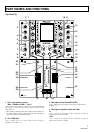
PART NAMES AND FUNCTIONS
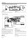
Touch Panel Display Contents
MAXMIN
TAP TAP
TIME/SELECT
MIX/DEPTH
EFFECT EFFECT
MAXMIN
TIME/SELECT
MIX/DEPTH
BANK 3
FX ADJ. FX ADJ.
BANK
EDIT
BANK
EDIT
FADER
CURVE
FA DE R
CURVE
OFF
ON
LOCK ON
PROFESSIONAL 2CHANNEL MIXER
DJM-909
BANK 2
BANK 1
BANK 1
BANK 2
BANK 3
EDIT 1 CH
TIME
AUTO
FOOT
LOW MID HI LOW MID HI
2000
120
AUTO
120
BPM
ms
EDIT 2 CH
PICH
0
BPM
%
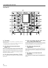
The touch panel display has four basic patterns (A-D). The
screen contents shown in the accompanying illustrations
depict one example of the basic patterns, while actual
displays may differ, depending on the kind of settings and
status involved.
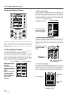
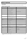
A. Effect type display (main page)
This display appears when the power is first turned on, or
when one of the BANK (1-3) buttons is pressed.
The effects for each channel are displayed as buttons, with
the currently selected button displayed in reverse
illumination (in this manual, indicated as black characters
against white background). Other displays show status of
foot switch, selected effect parameters, frequency bands
subject to effects, TIME display and BPM display.
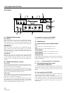
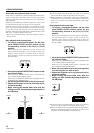
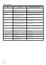
B. Effect select display
Hold the FADER CURVE/BANK EDIT button depressed for
about one second to change the screen to the main page
effect select menu (settable independently for each channel).
Rotate the TIME/SELECT dial to select the effect to be
allocated to each button from the list of 50 effects displayed
(see page 23, “Presetting effects”).
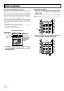
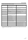
C. Effect parameter adjust display
Press the FX ADJ. button to display the effect parameter
adjust menu (settable independently for each channel). From
this menu, BPM AUTO can be selected. Also, effect
selection (cross fader / channel fader) can be selected for
fader type.
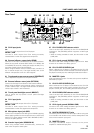
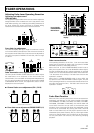
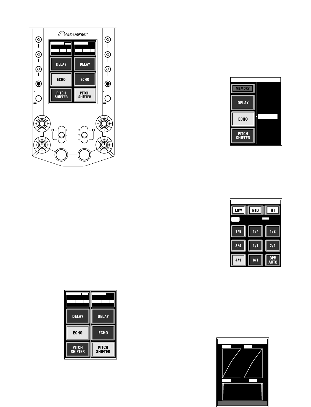
D. Fader status display
Press the FADER CURVE/BANK EDIT button to view the
fader status in a graphic display. By rotating the front panel
FADER CURVE dial, the various attenuation responses can
be set in 33 steps, and each step number also displayed. The
amount of cross fader lag is also given a numerical display.
FADER CURVE
NOR
M
AL
NOR
M
AL
NOR
M
AL
32 32
1616
FADER CUT LAG : 1 .0
mm
CF 1
CH 1 CH 2
CF 2
CH-1 fader data =
+ CH-2 fader
data
+ Cross fader
data
±
Cross fader lag data
(FADER CUT LAG)
When a foot switch is
connected, FOOT is
displayed.
The frequency band
subjected to effects is
highlighted (HI, MID,
LOW).
BPM count method is
displayed (AUTO).
Currently selected
effect is highlighted
(ECHO, PITCH
SHIFTER).
EDIT 1 CH
TIME
AUTO
FOOT
LOW MID HI LOW MID HI
2000
120
AUTO
120
BPM
ms
EDIT 2 CH
PICH
0
BPM
%
CH-1 side EFFECT + | = CH-2 side EFFECT
±
Select method of BPM
count (BPM AUTO).
TIME
AUTO
FOOT
2000120
BPM
ms
CH1
ECHO
Select frequency band
for effect (HI, MID,
LOW).
Select effect
parameter (4/1).
=
=
1.DEL
A
Y
2
CH 1 BANK EDIT
.ECHO
3.P
A
NEC
EC
EC
4.PIT
5.R
V
6.DK
7.ROL
D
L
Y
L
Effect list (ECHO)
≠
The button being
edited (here, ECHO)
appears highlighted.
(Example): CH-1 side.
=