


July 1992 9
Philips Semiconductors Preliminary specification
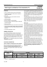
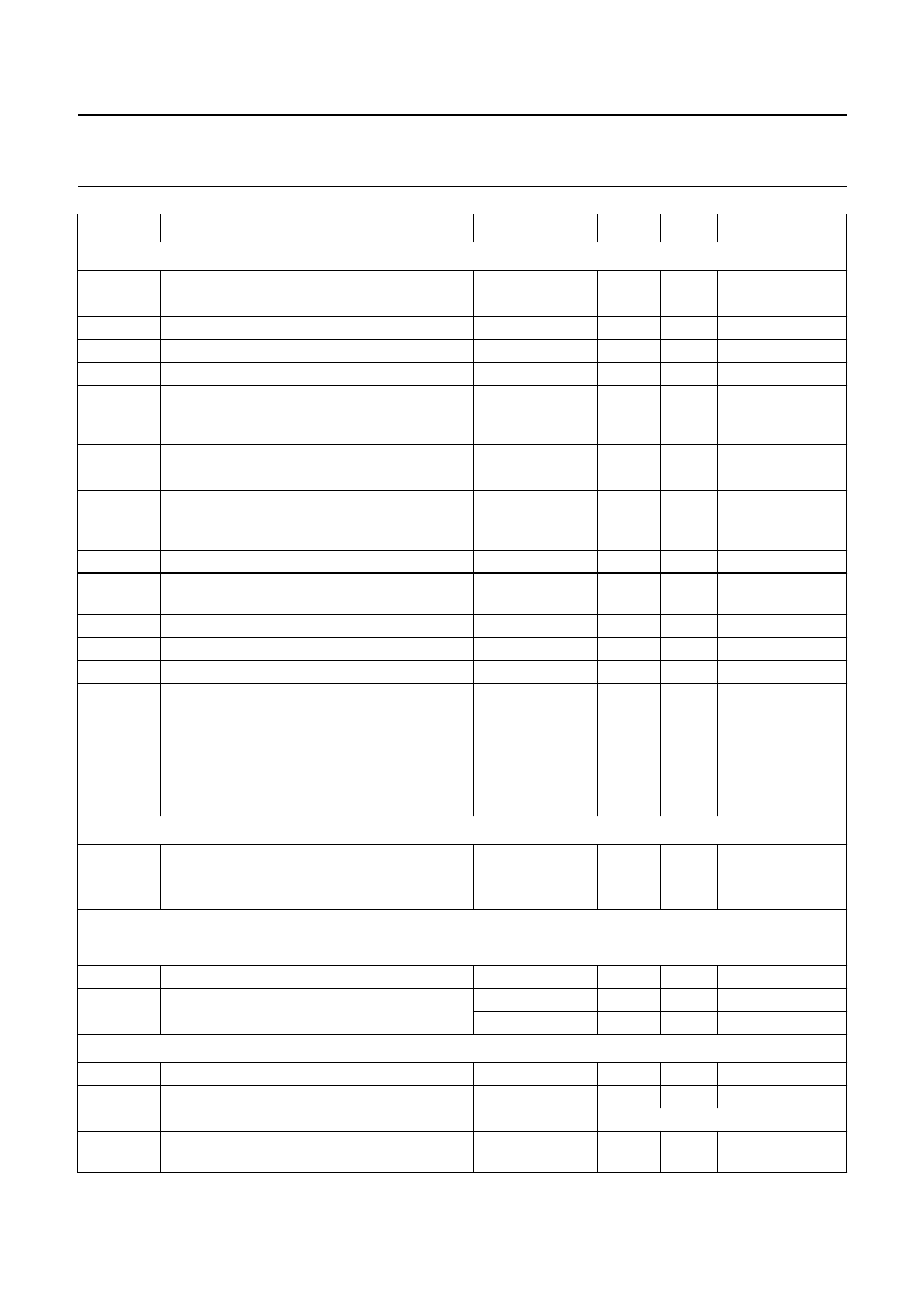
Small signal combination IC for black/white TV
TDA8303
TDA8303A
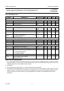
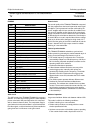
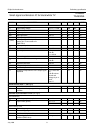
Sound circuit (note 12)
V
15
input limiting voltage V
O(max)
= −3 dB − 400 800 µV
R
15
input resistance − 2.6 − kΩ
C
15
input capacitance − 6 − pF
AMS AM suppression note 13 53 58 − dB
V
12(RMS)
AF output signal (RMS value) note 14 400 600 800 mV
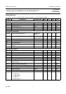
V
12(RMS)
AF output signal when pin 11 is used as a
starting pin or connected to V
P
(RMS value)
∆f = 50 kHz 500 900 1500 mV
Z
12
AF output impedance − 25 100 Ω
THD total harmonic distortion note 15 − 0.5 2 %
RR ripple rejection volume control
−20 dB;
f
k
= 100 Hz
− 35 − dB
V
12
output voltage when muted − 2.5 − V
V
12
output level shift due to muting volume control
−20 dB
−−0.5 dB
S/N signal-to-noise ratio note 16 − 47 − dB
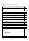
V
11
voltage with pin 11 disconnected − 6 − V
I
11
current with pin 11 short-circuited to ground − 1 − mA
V
12
temperature dependence of the output signal
amplitude
T
amb
= 20 to 65
°C;
−30 dB volume
control and
voltage of pin 11
fixed;
note 17
− 2.5 − dB
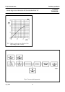
Volume control (note 17; see Fig.8)
R
11
external control resistor note 17 − 4.7 − kΩ
OSS suppression of output signal during mute
condition
60 66 − dB
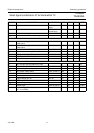
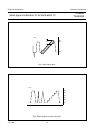
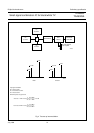
Horizontal synchronization circuit (see Fig.9)
SYNC SEPARATOR
V
25
required sync pulse amplitude note 20 200 750 − mV
I
25
input current (pin 25) V
25
> 5 V − 8 −µA
V
25
= 0 V − 10 − mA
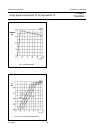
FIRST CONTROL LOOP
±∆f PLL holding range − 1500 2000 Hz
±∆f PLL catching range 600 1500 − Hz
control sensitivity to oscillator note 21 see Fig.10
V
8-9
IF input signal at which the time constant is
switched (RMS value)
strong-to-weak − 2.2 − mV
SYMBOL PARAMETER CONDITIONS MIN. TYP. MAX. UNIT