


July 1992 7
Philips Semiconductors Preliminary specification
Small signal combination IC for black/white TV
TDA8303
TDA8303A
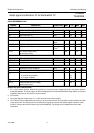
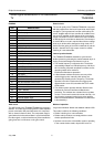
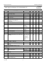
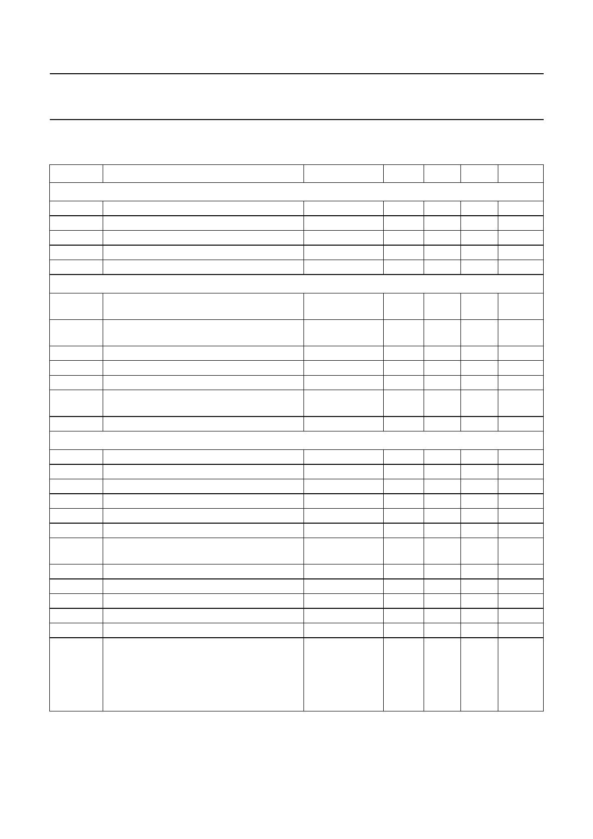
CHARACTERISTICS
V
P
= 12 V;T
amb
= 25 °C; carrier 38.9 MHz negative modulation, unless otherwise specified
SYMBOL PARAMETER CONDITIONS MIN. TYP. MAX. UNIT
Supply (pin 7)
V
P
supply voltage range 9.5 12 13.2 V
I
P
supply current no input 90 125 160 mA
I
11
start current (pin 11) note 1 − 6.5 9 mA
V
11
start voltage horizontal oscillator 9.5 −−V
V
11
start protection level I
11
= 12 mA −−16.5 V
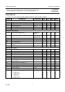
IF Amplifier (pins 8 and 9)
V
8-9(RMS)
input sensitivity (RMS value) at 38.9 MHz;
note 2
25 40 65 µV
V
8-9(RMS)
input sensitivity (RMS value) at 45.75 MHz;
notes 2 and 25
25 40 65 µV
R
8-9
differential input resistance note 3 − 1300 −Ω
C
8-9
differential input capacitance note 3 − 5 − pF
G
8-9
gain control range − 74 − dB
∆V
17
output signal expansion for 46 dB input signal
variation
note 4 − 1 − dB
V
8-9
maximum input signal 100 170 − mV
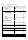
Video Amplifier (note 5)
V
17
zero signal output level note 6 − 5.4 − V
V
17
peak sync level 2.3 2.5 2.7 V
V
17
video output signal amplitude note 7 2.3 2.65 3.0 V
V
17
white spot threshold level − 5.7 − V
V
17
white spot insertion level − 3.8 − V
Z
17
video output impedance − 25 −Ω
I
17
internal bias current of npn emitter follower
output transistor
1.4 1.8 − mA
I
source
maximum source current (pin 17) 10 −−mA
B bandwidth of demodulated output signal 5 7 − MHz
G
17
differential gain note 8 − 48%
ϕ differential phase note 8 − 2 5 deg.
NL video non linearity note 9 − 25%
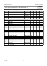
intermodulation note 10
1.1 MHz; blue 50 60 − dB
1.1 MHz; yellow 50 60 − dB
3.3 MHz; blue 55 65 − dB
3.3 MHz; yellow 55 65 − dB