


July 1992 6
Philips Semiconductors Preliminary specification
Small signal combination IC for black/white TV
TDA8303
TDA8303A
Narrow window mode: divider ratio between 522 and 528
(60 Hz); or 622 and 628 (50 Hz).
• The divider system switches over to narrow window
mode when the up/down counter has reached his
maximum value of 15 approved vertical sync pulses
• When the divider operates in the narrow window mode
and a vertical sync pulse is missing within the window,
the divider is reset at the end of that window and the
counter value is decreased by 1
• At a counter value below 10 the divider system switches
over to the large window mode
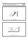
• The divider system also generates an anti-top-flutter
pulse which inhibits the phase 1 detector during the
vertical sync pulse. The pulse width is dependent on the
divider mode. For the large window mode the start is
generated at the reset of the divider. In the narrow
window mode the anti-top-flutter pulse starts at the
beginning of the first equalizing pulse. The
anti-top-flutter pulse ends at count 10 for the 50 Hz
mode and count 12 for the 60 Hz mode
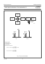
VCR switch
An extra time constant switch in the horizontal phase
detector makes an external VCR switch redundant. The
time constant is automatically switched depending on the
signal strength of the IF input (pins 8/9) and the
coincidence detector.
When a strong signal is detected (V
8/9
> 2.2 mV) and the
circuit is synchronized the time constant of the phase
detector is optimum for VCR playback, a fast time constant
during the vertical retrace to correct head errors of the
VCR and during scan a sufficient time constant to correct
fluctuations of the horizontal sync
During weak signal and synchronized conditions the time
constant is enlarged and the phase detector is gated. This
ensures a stable display which is not disturbed by the
noise in the video signal. When the circuit is not
synchronized the time constant is fast and not gated to
ensure a short catching time.
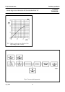
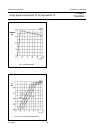
Combination of DC volume control and start-up
feature
Pin 11 of the IC can be used as a DC volume control or as
a start-up feature of the horizontal oscillator/output circuit
dependent on the application.
Volume control is achieved by connecting a 4.7 kΩ
potentiometer or a DC voltage of 0 to 3 V to pin 11. When
a current of 9 mA is supplied to pin 11 the volume control
is set to a fixed output signal level and the circuit will
generate drive pulses for the horizontal deflection and the
main supply can be derived from the deflection.
Application when external video signals require
synchronization
The input to the sync separator is externally available via
pin 25. For normal application the video output signal at pin
17 is AC-coupled to the sync separator input. It is possible
to interrupt this connection and drive the sync separator
from other sources.
When external signals are applied to the sync separator
the connections between the two parts must be
interrupted. This can be achieved by connecting pin 22 to
ground, which results in the following conditions:
• AGC detector is not gated
• Mute circuit not active, sound channel remains switched
on
• Phase detector 1 has an optimum time constant for
external video sources and is not gated
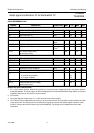
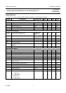
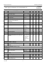
LIMITING VALUES
In accordance with the Absolute Maximum System (IEC 134)
SYMBOL PARAMETER MIN. MAX. UNIT
V
P
supply voltage (pin 7) − 13.2 V
P
tot
total power dissipation − 2.3 W
T
stg
storage temperature range −55 +150 °C
T
amb
operating ambient temperature range −25 +65 °C