


July 1992 11
Philips Semiconductors Preliminary specification
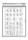
Small signal combination IC for black/white TV
TDA8303
TDA8303A
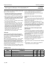
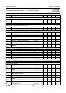
Notes to the characteristics
1. Pin 11 has a double function. When during switch-on a current of 9 mA is supplied to this pin, it is used to start the
horizontal oscillator. The main supply can then be obtained from the horizontal deflection stage. When no current is
supplied to this pin it can be used as a volume control.
2. On set AGC.
3. The input impedance has been chosen such that a SAW filter can be employed.
4. Measured with 0 dB = 450 µV.
5. Measured at 10 mV RMS top sync input signal.
6. Projected zero point; i.e. with switched demodulator.
7. White 10% of the top sync amplitude.
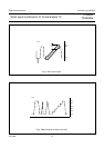
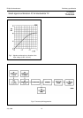
8. Measured according to the test line illustrated by Fig.2. The differential gain is expressed as a percentage of the
difference in peak amplitudes between the largest and smallest value relative to the subcarrier amplitude at blanking
level. The differential phase is defined as the difference in degrees between the largest and smallest phase angle.
The differential gain and phase are measured with a DSB signal.
9. This figure is valid for the complete video signal amplitude (peak white-to-black); see Fig.3. The non−linearity is
expressed as a percentage of the maximum deviation of a luminance step from the mean step, with respect to the
mean step.
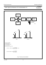
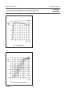
10. The test set−up and input conditions are illustrated by Fig.4. The figures are measured at an input signal of 10 mV
RMS.
11. Measured with a source impedance of 75Ω.
12. The sound circuit is measured (unless otherwise specified) with an input signal of V
15
of 50 mV RMS, a carrier
frequency of 5.5 MHz at a ∆f of 27.5 kHz. The QL of the demodulator tuned circuit is 16 and the volume control is
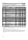
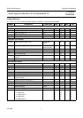
Vertical circuit (note 24)
V
ERTICAL RAMP GENERATOR
I
2
input current during scan −−2µA
I
2
discharge current during retrace − 0.8 − mA
V
2(p−p)
sawtooth amplitude (peak-to-peak value) − 1.9 − V
t interlace timing of the internal pulses 30 32 34 µs
V
ERTICAL OUTPUT
I
3
available output current V
3
= 4 V −−3mA
V
3
maximum available output voltage I
3
= 0.1 mA 4.4 5 − V
VERTICAL FEEDBACK INPUT
V
4
DC input voltage 2.9 3.3 3.7 V
V
4(p−p)
AC input voltage (peak-to-peak value) − 1 − V
I
4
input current −−12 µA
∆t
p
internal pre-correction to sawtooth − 3 − %
deviation amplitude 50/60 Hz −−4%
temperature dependency of the amplitude T
amb
= 20 to
65 °C
−−2%
SYMBOL PARAMETER CONDITIONS MIN. TYP. MAX. UNIT
The signal-to-noise ratio = 20
V
O
black-to-white
V
nRMS()
atB=5MHz
-----------------------------------------------------------log