


24 Wiring Inspection
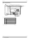
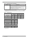
Table 1 Power Wiring Terminals - Factory Supplied
UPS Module Rating
kVA
Connection Type
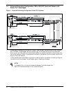
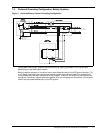
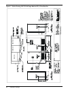
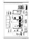
500-750 kVA Bus bars for connecting hardware (with 3/8” holes on 1.75” centers) are provided
for bypass input, critical load output and DC wiring terminations. DC bus bars for
625-750 kVA modules are designed for top entry and are located adjacent to the
input circuit breaker. Rectifier input wiring is top-entry, directly to lugs on top of
the input circuit breaker. Field-supplied lugs are required.
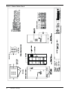
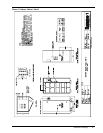
EXCEPTION: 500 kVA UPS modules with the 6-pulse rectifier and no input
isolation transformer have rectifier input bus bars exactly like those described
above for bypass and critical load termination.
Use 75°C copper wire. Select wire size based on the ampacities in Table 310-16 (see Table 3 of this manual)
and associated notes of the National Electrical Code (NFPA 70).
Use commercially available solderless lugs for the wire size required for your application. Refer to Appendix B
- Field Supplied Lugs. Connect wire to the lug using tool and procedure specified by the lug manufacturer.
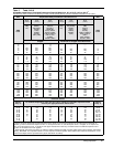
Table 2 Torque Specifications
Nut and Bolt Combinations
Bolt Shaft Size
Grade 2
Standard
Electrical Connections
with Belleville Washers
Lb-in N-m Lb-in N-m
1/4 53 6.0 46 5.2
5/16 107 12 60 6.8
3/8 192 22 95 11
1/2 428 48 256 29
Circuit Breakers With Compression Lugs (For Power Wiring)
Cable Size or Range Lb-in N-m
#6 - #4 100 11
#3 - #1 125 14
1/0 - 2/0 150 17
3/0 - 200 MCM 200 23
250 - 400 MCM 250 28
500 - 700 MCM 300 34
Terminal Block Compression Lugs (For Control Wiring)
AWG Wire Size or Range Lb-in N-m
#22 - #14 3.5 to 5.3 0.4 to 0.6
Use the values in this table unless the equipment is labeled with a
different torque value.