


14 Configuring Your Ground and Neutral Connections
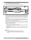
7.2 Alternative Grounding Configuration, 480 or 600 VAC Input and Output,
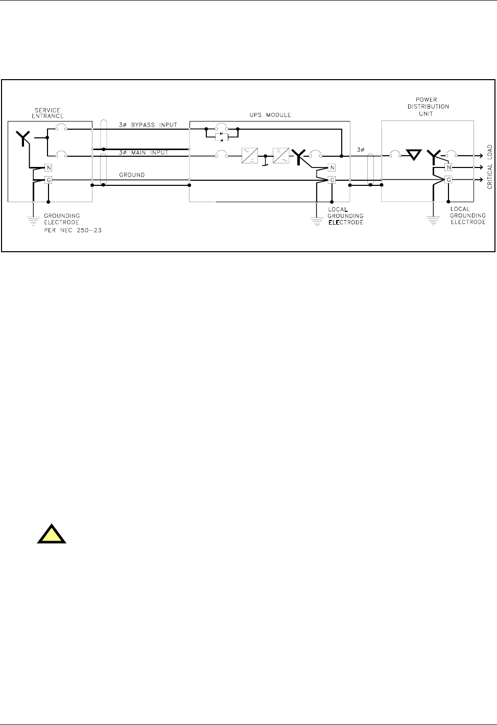
Isolated Power Distribution Units, Wye-Connected Service
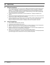
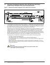
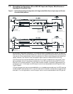
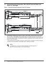
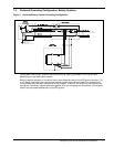
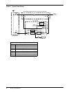
Figure 2 Alternative Grounding Configuration, 480 or 600 VAC input and output
This configuration is similar to that shown in Section 7.1, except that the service entrance neutral
is not brought into the UPS module. In this configuration, the UPS output transformer is consid-
ered a separately derived source. The UPS module neutral is bonded to the UPS ground, which is
connected to a local grounding electrode in accordance with NEC 250-26.
Please note that this configuration represents a price/performance trade-off. Whenever the UPS
module transfers to or from bypass, two AC sources (input and bypass) are briefly connected
together and circulating current must flow. In the previous configuration, the current flows
through the neutral conductor. In this configuration, the current flows through the ground path,
possibly tripping ground fault interruptors (GFIs) and distorting the bypass waveform reference.
Proper adjustment of ground fault interrupters is necessary to avoid unwanted tripping.
This configuration is reserved for those applications which meet all the following criteria:
• The facility has Wye-connected service
• The module rectifier input and bypass input are fed from the same source
• The connected load is strictly 3-wire (such as one or more PDUs) and does not require a neu-
tral from the UPS
• Special precautions are taken to prevent tripping the ground fault interruptors. The time
delay should be set to at least 30 cycles to prevent tripping when the UPS performs a transfer
or retransfer operation.
!
CAUTION
Failure to properly set the ground fault interruptors could cause
loss of power to the critical load.