6
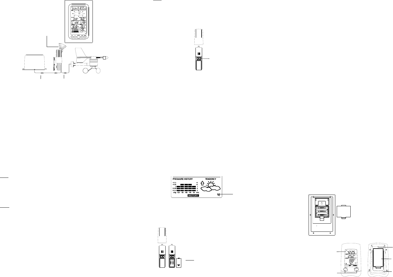
Cable connection
between the wind sensor
and the thermo-hygro
sensor
Cable connection
between the rain sensor
and the thermo-hygro
sensor
Wireless transmission
at 915 MHz - thermo-
hygro sensor to the
Weather Center
Weather Center
Wind sensor
Rain sensor
SETTING UP:
7
Note:
When putting the Weather Center into operation, it is important to perform in close
proximity (e.g. on a table) a complete wiring and set-up of the system. This step is
important to test all components for correct function before placing and mounting
them at their final destinations (See Positioning below)
1. Unwind the cables of the Rain and the Wind sensors. Connect the Rain and the
Wind sensors to the Thermo-hygro sensor by plugging the connector heads of
the two sensors into the appropriate sockets of the Thermo-hygro sensor.
2. First insert the batteries into the Thermo-hygro sensor (see “How to install and
replace the batteries into the Thermo-hygro sensor“ below).
3. Then insert the batteries into the Weather Center (see “How to install and
replace the batteries into the Weather Center” below). Once the batteries are
installed in the Weather Center, all segments of the LCD will light up briefly and
a short signal tone will be heard. It will then display the time as 12:00, the date
Sockets for wind
and rain sensor
8
as 1.1.05, the weather icons, and air pressure value. "- - -" will be shown for
outdoor data.
4. Afterwards, the Weather Center will start receiving data from the transmitter.
The outdoor temperature, humidity wind chill and wind speed should then be
displayed on the Weather Center. If this does not happen after 30 seconds, the
batteries will need to be removed from both units. You will have to start again
from step 1.
5. You may then check all cables for correct connection and all components for
correct function by manually turning the wind-gauge, moving the weather-vane,
tilting the rain sensor to hear the impact of the internally moving seesaw, etc
(See Positioning below).
6. Time and date shall be manually set (See Manual Setting below).
7. After the Weather Center has been checked for correct function with regard to
the above points and found fit, the initial set up of the weather station system is
finished and the mounting of the system components can take place. It must be
ensured however that all components work properly together at their chosen
mounting or standing locations. If e.g. there appear to be problems with the 915
MHz radio transmission, they can mostly be overcome by slightly changing the
mounting locations.
8. Insert the batteries into the Bonus Receiver (see “How to install and replace
the batteries into the Bonus Receiver” below).
9. Once the batteries are installed, all segments of the LCD will light up briefly. It
will then display the time as 12:00 and the indoor temperature.
10. The outdoor temperature and humidity will be display after reception of data
from the transmitter. If this does not happen after 1 minute, the batteries will
need to be removed from all the units. You will have to start again from step 1.
Note: Please refer to the “Bonus Receiver functions and settings” below.
9
Note:
The radio communication between the receiver and the transmitter in the open field
reaches distances of max 330 feet, provided there are no interfering obstacles such
as buildings, trees, vehicles, high voltage lines, etc.
11. Radio interferences created by PC screens, radios or TV sets can in some
cases entirely cut off radio communication. Please take this into consideration
when choosing standing or mounting locations.
Note :
• After batteries are installed in the transmitter, install the batteries in the weather
center and the bonus receiver to receive the signal from the transmitter as soon
as possible. If the weather center is powered more than 5 hours after the
transmitter is powered, the weather center will never receive signal successfully
from this transmitter. In this case, user will need to reinstall the batteries from
the transmitter to redo set-up procedure.
• After batteries are installed, there will be synchronization between weather
center and the transmitter. At this time, the signal reception icon will be blinking.
When the signal is successfully received by the weather center, the icon will be
switched on. (If it is not successful, the icon will not be shown in LCD) So the
user can easily see whether the last reception was successful (icon on) or not
(icon off). On the other hand, the short blinking of the icon shows that a
reception is in progress.
10
• If the signal reception is not successful on the first frequency (915MHz) for 14
seconds, the frequency is changed to 920MHz and the learning is tried another
14 seconds. If still not successful the reception is tried for 14 seconds on
910MHz. This will also be done for re-synchronization.
HOW TO INSTALL AND REPLACE THE BATTERIES INTO THE
THERMO-HYGRO SENSOR
The outdoor Thermo-hygro sensor works with 2 x “AA”, IEC
LR6 1.5V batteries. To install and replace the batteries, please
follow the steps below:
1.Uninstall the rain cover of the transmitter.
2.Remover the battery compartment cover.
3.Insert the batteries, observing the correct polarity (see the
marking in the battery compartment).
4.Replace the battery cover and the rain cover onto the unit.
Note:
In the event of changing batteries in any of the units, all units
need to be reset by following the setting up procedures. This is
because a random security code is assigned by the thermo-
Transmitter signal
reception icon
11
hygro sensor at start-up and this code must be received and stored by the Weather
Center in the first 30 seconds of power being supplied to it.
HOW TO INSTALL AND REPLACE THE BATTERIES INTO THE
WEATHER CENTER
The Weather Center works with 3 x AA, IEC LR6,
1.5V batteries. When the batteries need to be
replaced, the low battery symbol will appear on the
LCD.
To install and replace the batteries, please follow
the steps below:
1. Remove the battery compartment cover.
2. Insert the batteries observing the correct
polarity (see the marking in the battery
compartment).
3. Replace the battery cover.
HOW TO INSTALL AND REPLACE THE BATTERIES INTO THE BONUS
RECEIVER
LCD
Dis
la
Function Keys
Battery compartment
cover
Foldout stand
Hanging hole


