


HP StorageWorks Carrier-Grade 2324fc Modular Smart Array user guide 51
Sensor locations
The storage system monitors conditions at different points within each enclosure to alert you to problems.
Power, cooling fan, temperature, and voltage sensors are located at key points in the enclosure. In each
controller module and expansion module, the enclosure management processor (EMP) monitors the status
of these sensors to perform SCSI enclosure services (SES) functions.
The following sections describe each element and its sensors.
Power supply sensors
Each enclosure has two fully redundant power supplies with load-sharing capabilities. The power supply
sensors described in the following table monitor the voltage, current, temperature, and fans in each power
supply. If the power supply sensors report a voltage that is under or over the threshold, check the input
voltage.
Cooling fan sensors
Each power supply includes two fans. The normal range for fan speed is 4000 to 6000 RPM. When a
fan’s speed drops below 4000 RPM, the EMP considers it a failure and posts an alarm in the storage
system’s event log. The following table lists the description, location, and alarm condition for each fan. If
the fan speed remains under the 4000 RPM threshold, the internal enclosure temperature may continue to
rise. Replace the power supply reporting the fault.
During a shutdown, the cooling fans do not shut off. This allows the enclosure to continue cooling.
Temperature sensors
Extreme high and low temperatures can cause significant damage if they go unnoticed. Each controller
module has six temperature sensors. Of these, if the CPU or FPGA temperature reaches a shutdown value,
the controller module is automatically shut down. Each power supply has one temperature sensor.
When a temperature fault is reported, it must be remedied as quickly as possible to avoid system damage.
This can be done by warming or cooling the installation location.
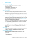
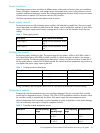
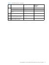
Table 6 Power supply sensors
Description Event/Fault ID LED condition
Power supply 1 Voltage, current, temperature, or fan
fault
Power supply 2 Votlage, current, temperature, or fan
fault
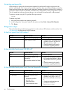
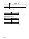
Table 7 Cooling fan sensor descriptions
Description Location Event/Fault ID LED condition
Fan 1 Power supply 1 < 4000 RPM
Fan 2 Power supply 1 < 4000 RPM
Fan 3 Power supply 2 < 4000 RPM
Fan 4 Power supply 2 < 4000 RPM
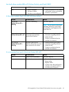
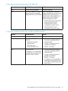
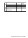
Table 8 Controller module temperature sensors
Description Normal operating
range
Warning
operating range
Critical operating
range
Shutdown values
CPU temperature 3–88C 0–3C,
88–90C
> 90C 0C
100C
FPGA temperature 3–97C 0–3C,
97–100C
None 0C
100C