


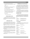
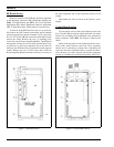

REAR COVER ASSEMBLY
The Rear Cover Assembly houses the RF Board in the
die-cast aluminum case. The complete assembly consists of
the VHF RF Board, aluminum case, top antenna jack, side
(UDC) antenna jack and various hardware.
The RF Board’s circuitry includes the transmitter, re-
ceiver and the frequency synthesizer. This FM circuitry is
under complete control of the microprocessor circuits. Con-
trolling data sent to this assembly from the Control Board
includes serial synthesizer data loading, transmitter/receiver
enabling and a transmitter power level signal. The RF Board
outputs the demodulated audio and a synthesizer lock status
line to the Control Board. During transmitter operation, the
RF power appears at the top antenna jack (or the UDC jack
if the appropriate adapter plug is inserted). The Rear Cover
Assembly maintenance manual contains a detailed circuit
analysis, mechanical, outline and schematic diagrams for
this assembly.
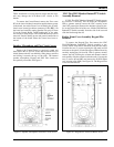
FRONT COVER ASSEMBLY
The Front Cover Assembly houses all of the operating
controls and the digital control circuitry for the radio. Board
assemblies used in this assembly include the Control and
LCD Boards and flex circuits include the Keypad, UDC and
Speaker Flex circuits. The speaker, microphone and Battery
Plate are also a part of this assembly. The complete assem-
bly is housed in the die-cast aluminum front cover. Scan and
System model radios are equipped with a keypad on the
front panel.
The Control Board located in the Front Cover Assembly
is the largest and most complex board in the Front Cover
Assembly. It contains all microcomputer and audio circuitry
which controls the radio. See the maintenance manuals spe-
cific to the Control Board or the Front Cover Assembly for
service information on the related assembly.
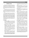
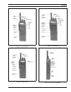
ANTENNAS
Antennas are selected based on the operating frequency
range of the radio. Table 1 lists the available antennas which
mount in the antenna jack on the top of the radio. An exter-
nal antenna can be mounted to the unit via the UDC. When
an antenna is connected to the UDC, the antenna on the top
of the radio is disabled.
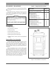
BATTERY PACKS
The battery pack connects to the bottom of the unit and
delivers a nominal 7.5 Volts dc to the radio. A recessed
on/off switch for the radio is located on the battery pack. An
internal fuse located in the radio’s Battery Plate protects the
radio and battery from excessive current draw. The battery
packs are available in several different capacities and sizes.
Radio contacts located on the top of the pack include
switched power, ground, the speaker enabling contacts and a
continuous power contact In addition, four contacts are lo-
cated on the rear of the battery pack. These four contacts
provide connections to the slip-in type chargers or vehicular
chargers/repeaters while the battery pack is still connected
to the unit The battery charging contacts are diode protected
from external shorts.
The chargers utilize an internal thermistor in the battery
pack to sense temperature and automatically control charge
rate of the battery. This allows for a maximum charge rate
without overheating the battery pack. All battery packs can
be charged in less than 1 1/2 hours with the rapid type
chargers. Nominal full charge time in a standard charger is
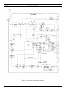
14 hours. The Service Section contains a detailed outline
and schematic diagram of a typical battery pack. Further
service information for the battery packs is also presented in
the Service Section.
Chargers are available with nominal charge times of one
hour (rapid) and fourteen hours (standard). Combinations
include single (1) and multi (5 or 6) position, standard and
rapid charge units. In addition, the vehicular chargers simul-
taneously charge the battery while the radio is operating.
The battery packs should be fully charged in an appro-
priate charger before they are placed into service. This ap-
plies to new battery packs received from the factory and to
battery packs that have been stored for long periods of time.
A fully charged battery pack should have an open-terminal
voltage greater than 7.5 Volts (typically 9.0 Vdc). A battery
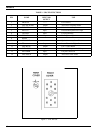
TABLE 1 -VHF ANTENNAS
USABLE FREQ.
RANGE (MHz)
OPTION
NUMBER PART NUMBER TYPE
COLOR
BANDS
136-151 PANC1B 19B234804P1 Helical Brown
146-162 PANC1C 19B234804P2 Helical Red
157 - 174 PANC1D 19B234804P3 Helical Orange
LBI-38378
8