


Later Front Cover Assembly Keypad Flex Removal
To remove the Keypad Flex, first remove the UDC
Flex/UDC/Monitor Button/PTT Switch assembly as pre-
viously stated. Next remove the screw securing the emer-
gency switch support (G) then remove the support. Remove
the knobs using the hex driver. With a spanner wrench, re-
move the nuts securing the volume and channel controls and
carefully slide the controls inside the radio. Unscrew the
two (2) screws that secure the J10/P10 connection at the
bottom of the LCD Board. Remove the screws, the plate and
the rubber pad. The Keypad Flex is now free for removal.
Speaker Flex Removal
In order to replace the Speaker Flex, it must be un-sol-
dered from the speaker and the Battery Plate.
LCD Board Access
To remove the LCD Board, partial removal (actually re-
positioning of the top areas) of the Keypad Flex is required.
UDC Flex/UDC/Monitor Button/PTT Switch assembly re-
moval is not necessary.
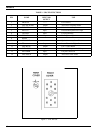
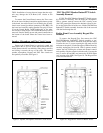
After the top areas of the Keypad Flex have been freed
as previously outlined, the LCD Board can be removed. At
this point is the disassembly process an earlier Front Cover
Assembly has two (2) screws on the left side as view from
the back (J and JJ) and a later assembly has a single screw
in the upper left-hand side (J). See Figure 10.
Printed in U.S.A.
LBI-38378
18