Page 9SKU 97427 For technical questions, please call 1-800-444-3353.
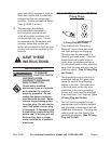
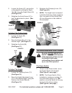
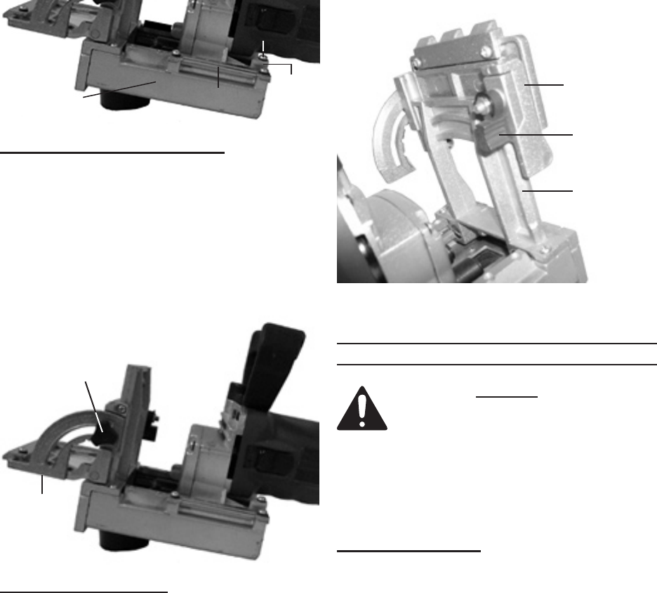
Loosen the Screw (47), and set the 2.
cutting depth by sliding the Depth
Tab (48) along the Depth Ruler (49).
(See Figure B.)
Retighten the Knob Screw (47) to 3.
lock the adjustment in place. (See
Figure B.)
MOTOR BASE (16)
Knob
SCREW
(47)
DEPTH
TAB
(48)
DEPTH RULER
(49)
FIGURE B
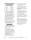
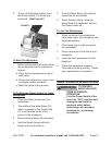
To Adjust The Cutting Angle:
Loosen the Knob (59). 1.
(See Figure C.)
Move the Angle Stop (3) to the 2.
desired angle. (See Figure C.)
Retighten the Knob (59). 3.
(See Figure C.)
FIGURE C
KNOB
(59)
ANGLE
STOP
(3)
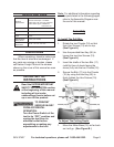
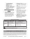
To Adjust The Height:
Loosen the Clamping Lever (12). 1.
(See Figure D.)
Move the Height Adjustment Lever 2.
(14) to the desired height, using the
Scale on the Guide Plate (8).
(See Figure D.)
Retighten the Clamping Lever (12). 3.
(See Figure D.)
NOTE: 4. The height must correspond
to half the thickness of the workpiece.
Also, the groove of the Guide Plate
(8) must always be in the middle of
the workpiece.
CLAMPING
LEVER
(12)
GUIDE
PLATE
(8)
HEIGHT
ADJUSTMENT
(14)
FIGURE D
OPERATING INSTRUCTIONS
Read the ENTIRE IMPORTANT
SAFETY INFORMATION section
at the beginning of this manual
including all text under
subheadings therein before set
up or use of this product.
The Power Switch:
To turn on the Dowel Jointer, move 1.
the Power Switch (74) forward.
(See Figure E, next page.)
NOTE: 2. The Power Switch (74) is
lockable for continuous running. To
lock the Power Switch in its “ON”
position, move the Switch all the way
forward until it locks in place.
(See Figure E, next page.)


