


2-8
Operation
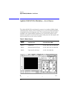
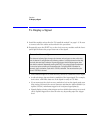
To Display a Signal
To Display a Signal
1
Install the module as described in “To install the module” on page 1-3. Be sure
to connect all of the cables as described in the procedure.
2
Repeatedly press the
SELECT
key on the clock recovery module until the front-
panel light indicates the proper data rate of the signal.
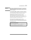
• If the
UNLOCKED
light
is on, clock recovery
cannot be established on the signal.
• Avoid selecting a data rate that is a multiple of the input signal. For example,
don’t select a 622 Mb/s data rate if the signal is really at 155 Mb/s.
• If you cannot get the clock recovery module to lock on the signal, make sure
that you have selected the correct data rate and that the Agilent 83480A (or
Agilent 54750A) mainframe trigger level is adjusted appropriately.
• Signals displayed using a data trigger are less reliable than using a recovered
clock. Signals triggered on data can also vary depending upon the trigger
level.
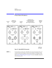
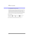
Green and red data-rate lights
The data-rate indicator lights change color between red and green to show which data
rate is selected. A red light does
not
indicate a problem. A red light shows that the adja-
cent red data rate label is selected. A green light shows that the adjacent green data
rate label is selected. Repeatedly pressing the SELECT key cycles through the selections
in one color before switching to the opposite color. On Agilent 83491A modules for
example, the first selection cycle shows 155 Mb/s selected. The second section cycle
shows 1062 Mb/s selected.