


2-5
Operation
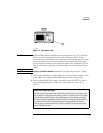
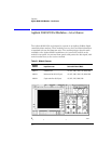
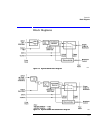
Front-Panel Features
UNLOCKED
indicator
This light shows when clock recovery cannot be established on the signal. If a
clock rate is selected, the trigger output to the mainframe
is
disabled to pre-
vent free-run triggering. However in bypass mode (
Trigger On Data
selected),
triggering is
not
disabled. When the
UNLOCKED
light is on, you can establish a
trigger on the data input to the reference receiver.
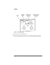
Auxiliary outputs
DATA
connector: This connector provides a fully regenerated version of the
input signal. It is intended for monitoring purposes only and
not
for rigorous
eye mask compliance testing. The frequency response does not conform to the
requirements for eye mask testing as described in ITU-T G.957 and Bellcore
GR-253-CORE. On Agilent 83492A and 83493A modules, this port is ampli-
tude stabilized for input signals greater than approximately –23 dBm.
CLOCK c
onnector: This connector provides the recovered clock signal. You can
use this signal to measure jitter transfer, because this output can track and fol-
low input data with very fast jitter; it has a wide bandwidth jitter transfer func-
tion when compared to the recovered clock signal which is routed through a
rear-panel connector to the mainframe for triggering. Note that the
CLOCK
Aux-
iliary Output
remains synchronized to input signals several dB below the onset of
errors at the
DATA
Auxiliary Output
.
Input and Output
connectors
The input connectors pass the digitally modulated signal to the receiver mod-
ule. The input signal, slightly attenuated and available at the
OUTPUT
connec-
tor, is connected to the input of any of the Agilent 83481,2,3,4,5,6, or 7
modules. The connectors on optical modules include adapters which can eas-
ily be changed to match the type of connectors that are used on your fiber-
optic cables. Refer to “Front-Panel Optical Adapters” on page 4-2 for a
description of the available adapters.
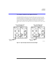
Green and red data-rate lights
The data-rate indicator lights change color between red and green to show which data
rate is selected. A red light does
not
indicate a problem. A red light shows that the adja-
cent red data rate label is selected. A green light shows that the adjacent green data
rate label is selected. Repeatedly pressing the SELECT key cycles through the selections
in one color before switching to the opposite color. On Agilent 83491A modules for
example, the first selection cycle shows 155 Mb/s selected. The second section cycle
shows 1062 Mb/s selected.