


2-3
Operation
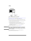
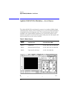
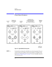
Agilent 83491/2/3A Modules—At a Glance
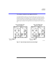
WARNING
Light energy can radiate from the front panel
OUTPUT
connectors on
Agilent 83492A and 83493A modules. The light emitted from these
connectors is the slightly attenuated light that is input to the front-
panel
INPUT
connector.
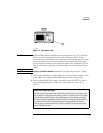
Use with Agilent 71603B or 71612B Error Performance Analyzers
The front-panel
Data
and
Clock
outputs provide electrical recovered clock and
regenerated data signals for simultaneous testing with other instruments,
such as the Agilent 71603B or 71612B error performance analyzers.
Multimode module and single-mode reference receivers
Agilent Technologies does
not
recommend using the Agilent 83492A multi-
mode module with single-mode reference receivers such as the
Agilent 83481A, 83482A, or 83485A,B modules. Connecting multimode to sin-
gle-mode fibers causes large reflections and insertion loss because of the
reduction of the optical fiber’s core from 62.5
µ
m to 9
µ
m.
Single-mode module and multimode reference receivers
It is acceptable to use an Agilent 83493A single-mode module with a multi-
mode reference receiver such as the Agilent 83486A module. This is true pro-
vided that single-mode fiber is connected to the Agilent 83493A module’s
front-panel
INPUT
connector.
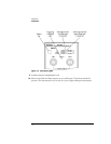
What you won’t find on these modules....
Unlike other modules designed to be used with the Agilent 83480A digital communica-
tions analyzer, the Agilent 83491/2/3A modules do not include Channel keys or menus.
Also, there are no GPIB programming commands for these modules.