


2-6
Operation
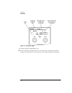
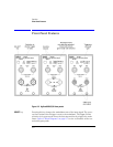
Front-Panel Features
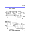
Recovered Clock
The recovered clock signal is routed directly to the Agilent 83480A mainframe
through the module’s rear panel. This output has a lower jitter modulation
bandwidth than the front-panel
CLOCK Auxiliary Output
.
Because of the reduced
jitter modulation bandwidth on the mainframe trigger signal, a more complete
view of the jitter on the waveform data is obtained.
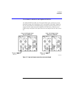
Multimode and single-mode connections
Agilent 83492A modules use multimode fiber. Connecting the output to the Optical
INPUT connector on Agilent 83481/2/5 single-mode modules results in large reflections
and insertion loss.
Agilent 83493A modules use 9/125
µ
m single-mode fiber. Connecting multimode fiber
to the Optical Input connector results in large reflections and insertion loss.