


5
4.0 LHS End Cap Installation
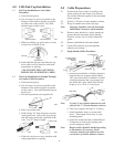
4.1 End Cap Installation on Cut Cables
Procedure:
a. Select desired port(s).
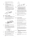
b. Cut off cone(s) as close as possible to the
diameter of the cable using the cut guides
on either side of the cone(s). See cable
diameter tape on back cover.
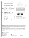
c. When not slitting cap, place piece of foam
in each slot on inside of cap.
Slit
5.0 Cable Preparations
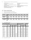
5.1 Position and secure cables according to the
splice opening for the closure size selected.
See closure dimension guide for the maximum
splice openings.
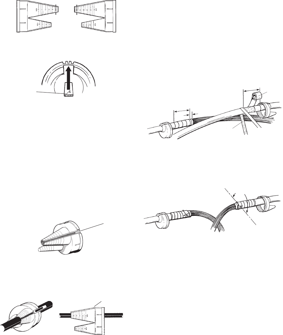
5.2 Scuff 6" (152 mm) of outer sheaths as shown.
5.3 Wrap all scuffed areas with vinyl tape.
Note: Vinyl tape should be removed from under
Shield Bond Connectors when installed.
5.4 Remove outer sheath for a splice opening no
greater than the maximum splice opening
listed for closure size in closure dimension
guide.
5.5 Remove shield flush with outer sheath.
5.6 Clean filled cable for good encapsulant
adhesion and sealing.
5.7 Single Sheath Cables Procedure:
d. Place cap around cable.
e. Slide locking "H" Strip into place over the
raised guide rails. Start at the large (body)
end and work towards the small end of the
cone. Cut "H" Strip to length.
f. Slide end cap down so not to interfere with
cable preparations or splicing.
Metric DesignationEnglish Designation
842844
842845
842847
842846
88T
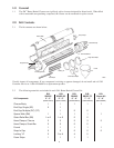
Core Wrapper
3/4" (19 mm)
6" (152mm) Scuffed
and Temporarily
Wrapped
Sheath Scuff
883655
6" (152mm) Scuff
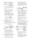
a. Insert base assemblies of shield connectors
between the core wrapper and the shield
180° apart. Insert base assemblies of shield
connectors between the core wrapper and
the shield 180° apart. Install first nut and
torque to 45 ± 5 in-lbs (5.2 ± 0.6 kg·m).
883657
180°
Single Sheath
Note: Use only 1 (one) sheath connector on each
cable for the 2" (50 mm) diameter closures.
b. Trim core wrapper, leaving 3/4" (19 mm).
c. Install insulation sleeve on strain relief
bar(s). Trim length if necessary to clear
mounting holes.
d. Install one strain relief bar on Shield Bond
Connectors (to hold splice opening and
provide temporary bond.)
Note: Branch cables should be bonded according
to illustrations. If necessary, shield
connector studs may be trimmed to clear
cover halves of smaller diameter closures.
"H" Strip in Place
4.2 End Cap Installation on Straight Through
or Express Cable Procedure:
a. Select desired port(s).
b. Cut off cone(s) as close as possible to the
diameter of the cable using the cut guides
on the cone(s). See cable diameter tape on
back cover.
c. Slit end cap between raised guide rails.
d. Push cable through port and slide end cap
down cable so not to interfere with cable
preparations or splicing.
DO NOT SLIT END CAP UNLESS
INSTALLING ON EXISTING CABLE.
Foam Tape
Inside End View
883656