12
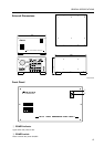
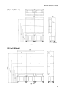
GENERAL SPECIFICATIONS
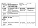
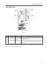
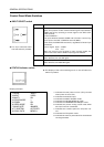
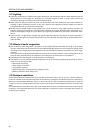
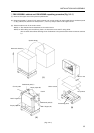
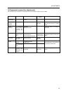
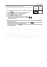
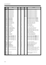
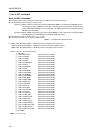
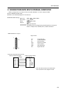
Control Panel Mode Switches
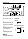
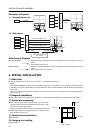
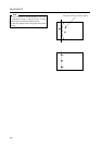
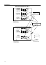
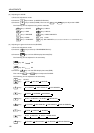
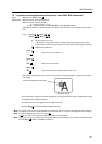
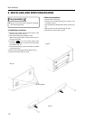
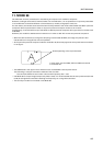
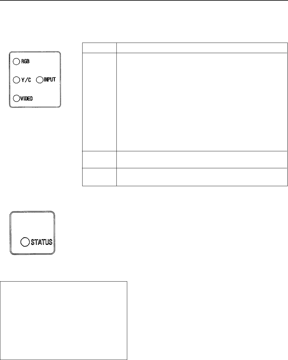
¶ INPUT SELECT switch
Position Function
VIDEO Selects the VIDEO input terminal. When selected, the VIDEO LED
lights. This position is also used for switching the input between
VIDEO and Y/C by inputting a control signal to the EXT. CON-
TROL terminal.
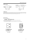
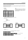
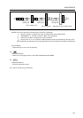
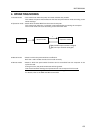
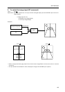
< EXT. CONTROL >
The input switches between VIDEO and Y/C when a control sig-
nal is input to the EXT. CONTROL terminal (BNC).
In this case, the VIDEO LED remains lit, regardless of which input
is selected.
Control signal Open : VIDEO
Low : Y/C
When the control input terminal is open (normal mode), the
open mode is set and the VIDEO input signal is selected.
Y/C The Y/C input terminal is selected.
When selected, the Y/C LED lights.
RGB The RGB input terminal is selected.
When selected, the RGB LED lights.
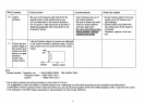
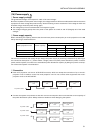
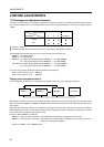
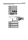
¶ The input switches each
time the switch is pressed.
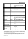
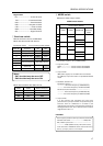
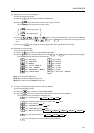
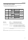
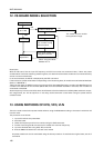
1.HOUR
2.INPUT
3.MULTI
4.COLOR MODE
5.COMBI.
6.VIDEO MODE
7.BAUD RATE
8.TV SYSTEM
9.CONV. DATA
1000 H
VIDEO
ON
1
ON
ON
4800BPS
AUTO/NTS
MEMO-1
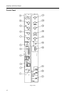
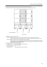
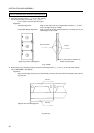
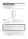
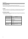
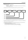
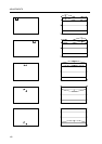
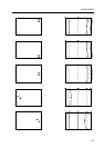
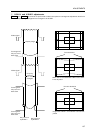
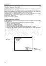
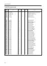
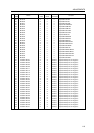
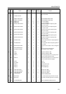
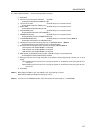
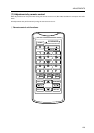
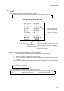
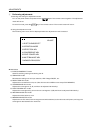
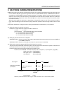
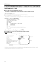
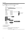
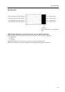
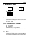
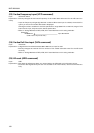
¶ STATUS indicator switch
Display example)
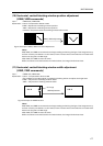
¶ The display of the various settings turns on and off when the
switch is pressed.
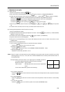
1: Indicates the total power on time. (Only counted
when power is set to ON.)
2: Indicates the selected input.
3: Indicates the MULTI ON/OFF mode.
4: Indicates the COLOR MODE 1/2 mode.
5: Indicates the COMBINATION ON/OFF mode.
6: Indicates the picture muting on/off mode when
the input function is switched.
7: Indicates the transfer speed for computer con-
trol.
8: Indicates the TV system mode.
9: Indicates the memory area status for the selected
convergence data.